TOOLSTICK540DC Silicon Laboratories Inc, TOOLSTICK540DC Datasheet - Page 75
TOOLSTICK540DC
Manufacturer Part Number
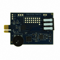
TOOLSTICK540DC
Description
DAUGHTER CARD TOOLSTICK F540
Manufacturer
Silicon Laboratories Inc
Series
ToolStickr
Type
MCUr
Datasheets
1.TOOLSTICK540DC.pdf
(274 pages)
2.TOOLSTICK540DC.pdf
(16 pages)
3.TOOLSTICK540DC.pdf
(12 pages)
Specifications of TOOLSTICK540DC
Contents
Daughter Card
Processor To Be Evaluated
C8051F54x
Processor Series
C8051F54x
Interface Type
USB
Operating Supply Voltage
2.7 V to 3.6 V
Lead Free Status / RoHS Status
Lead free / RoHS Compliant
For Use With/related Products
C8051F54x
For Use With
336-1345 - TOOLSTICK BASE ADAPTER336-1182 - ADAPTER USB DEBUG FOR C8051FXXX
Lead Free Status / Rohs Status
Lead free / RoHS Compliant
Other names
336-1717


With the CIP-51's maximum system clock at 50 MHz, it has a peak throughput of 50 MIPS. The CIP-51 has
a total of 109 instructions. The table below shows the total number of instructions that require each execu-
tion time.
Programming and Debugging Support
In-system programming of the Flash program memory and communication with on-chip debug support
logic is accomplished via the Silicon Labs 2-Wire Development Interface (C2).
The on-chip debug support logic facilitates full speed in-circuit debugging, allowing the setting of hardware
breakpoints, starting, stopping and single stepping through program execution (including interrupt service
routines), examination of the program's call stack, and reading/writing the contents of registers and mem-
ory. This method of on-chip debugging is completely non-intrusive, requiring no RAM, Stack, timers, or
other on-chip resources. C2 details can be found in Section “25. C2 Interface” on page 269.
The CIP-51 is supported by development tools from Silicon Labs and third party vendors. Silicon Labs pro-
vides an integrated development environment (IDE) including editor, debugger and programmer. The IDE's
debugger and programmer interface to the CIP-51 via the C2 interface to provide fast and efficient in-sys-
tem device programming and debugging. Third party macro assemblers and C compilers are also avail-
able.
Clocks to Execute
Number of Instructions
RESET
CLOCK
STOP
IDLE
1
26
ACCUMULATOR
Figure 10.1. CIP-51 Block Diagram
PROGRAM COUNTER (PC)
CONTROL
PSW
PRGM. ADDRESS REG.
LOGIC
POWER CONTROL
PC INCREMENTER
DATA POINTER
REGISTER
2
50
BUFFER
TMP1
PIPELINE
ALU
2/3
5
TMP2
Rev. 1.1
DATA BUS
DATA BUS
D8
D8
D8
3
14
A16
D8
D8
D8
D8
B REGISTER
REGISTER
INTERFACE
INTERFACE
INTERRUPT
INTERFACE
ADDRESS
MEMORY
SRAM
SFR
BUS
3/4
7
MEM_WRITE_DATA
SFR_WRITE_DATA
MEM_READ_DATA
STACK POINTER
SFR_READ_DATA
SRAM
MEM_ADDRESS
MEM_CONTROL
EMULATION_IRQ
SFR_ADDRESS
SFR_CONTROL
SYSTEM_IRQs
4
3
4/5
1
C8051F54x
5
2
8
1
75
Related parts for TOOLSTICK540DC
Image
Part Number
Description
Manufacturer
Datasheet
Request
R

Part Number:
Description:
KIT TOOL EVAL SYS IN A USB STICK
Manufacturer:
Silicon Laboratories Inc
Datasheet:

Part Number:
Description:
TOOLSTICK DEBUG ADAPTER
Manufacturer:
Silicon Laboratories Inc
Datasheet:

Part Number:
Description:
TOOLSTICK BASE ADAPTER
Manufacturer:
Silicon Laboratories Inc
Datasheet:

Part Number:
Description:
TOOLSTICK DAUGHTER CARD
Manufacturer:
Silicon Laboratories Inc
Datasheet:

Part Number:
Description:
TOOLSTICK DAUGHTER CARD
Manufacturer:
Silicon Laboratories Inc
Datasheet:

Part Number:
Description:
TOOLSTICK DAUGHTER CARD
Manufacturer:
Silicon Laboratories Inc
Datasheet:

Part Number:
Description:
TOOLSTICK PROGRAMMING ADAPTER
Manufacturer:
Silicon Laboratories Inc
Datasheet:

Part Number:
Description:
TOOLSTICK DAUGHTER CARD
Manufacturer:
Silicon Laboratories Inc
Datasheet:

Part Number:
Description:
KIT STARTER TOOLSTICK
Manufacturer:
Silicon Laboratories Inc
Datasheet:

Part Number:
Description:
KIT UNIVERSITY TOOLSTICK STARTER
Manufacturer:
Silicon Laboratories Inc
Datasheet:

Part Number:
Description:
DAUGHTER CARD TOOLSTICK F330
Manufacturer:
Silicon Laboratories Inc
Datasheet:

Part Number:
Description:
CARD DAUGHTER UNIVRSTY TOOLSTICK
Manufacturer:
Silicon Laboratories Inc
Datasheet:

Part Number:
Description:
DAUGHTER CARD TOOLSTICK F582
Manufacturer:
Silicon Laboratories Inc
Datasheet:

Part Number:
Description:
DAUGHTER CARD TOOLSTICK F500
Manufacturer:
Silicon Laboratories Inc
Datasheet:

Part Number:
Description:
DAUGHTER CARD TOOLSTICK F560
Manufacturer:
Silicon Laboratories Inc
Datasheet: