TOOLSTICK540DC Silicon Laboratories Inc, TOOLSTICK540DC Datasheet - Page 257
TOOLSTICK540DC
Manufacturer Part Number
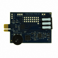
TOOLSTICK540DC
Description
DAUGHTER CARD TOOLSTICK F540
Manufacturer
Silicon Laboratories Inc
Series
ToolStickr
Type
MCUr
Datasheets
1.TOOLSTICK540DC.pdf
(274 pages)
2.TOOLSTICK540DC.pdf
(16 pages)
3.TOOLSTICK540DC.pdf
(12 pages)
Specifications of TOOLSTICK540DC
Contents
Daughter Card
Processor To Be Evaluated
C8051F54x
Processor Series
C8051F54x
Interface Type
USB
Operating Supply Voltage
2.7 V to 3.6 V
Lead Free Status / RoHS Status
Lead free / RoHS Compliant
For Use With/related Products
C8051F54x
For Use With
336-1345 - TOOLSTICK BASE ADAPTER336-1182 - ADAPTER USB DEBUG FOR C8051FXXX
Lead Free Status / Rohs Status
Lead free / RoHS Compliant
Other names
336-1717


24.3.5. 8-bit, 9-bit, 10-bit and 11-bit Pulse Width Modulator Modes
Each module can be used independently to generate a pulse width modulated (PWM) output on its associ-
ated CEXn pin. The frequency of the output is dependent on the timebase for the PCA counter/timer, and
the setting of the PWM cycle length (8, 9, 10 or 11-bits). For backwards-compatibility with the 8-bit PWM
mode available on other devices, the 8-bit PWM mode operates slightly different than 9, 10 and 11-bit
PWM modes. It is important to note that all channels configured for 8/9/10/11-bit PWM mode will use
the same cycle length. It is not possible to configure one channel for 8-bit PWM mode and another for 11-
bit mode (for example). However, other PCA channels can be configured to Pin Capture, High-Speed Out-
put, Software Timer, Frequency Output, or 16-bit PWM mode independently.
24.3.5.1. 8-bit Pulse Width Modulator Mode
The duty cycle of the PWM output signal in 8-bit PWM mode is varied using the module's PCA0CPLn cap-
ture/compare register. When the value in the low byte of the PCA counter/timer (PCA0L) is equal to the
value in PCA0CPLn, the output on the CEXn pin will be set. When the count value in PCA0L overflows, the
CEXn output will be reset (see Figure 24.8). Also, when the counter/timer low byte (PCA0L) overflows from
0xFF to 0x00, PCA0CPLn is reloaded automatically with the value stored in the module’s capture/compare
high byte (PCA0CPHn) without software intervention. Setting the ECOMn and PWMn bits in the
PCA0CPMn register, and setting the CLSEL bits in register PCA0PWM to 00b enables 8-Bit Pulse Width
Modulator mode. If the MATn bit is set to 1, the CCFn flag for the module will be set each time an 8-bit
comparator match (rising edge) occurs. The COVF flag in PCA0PWM can be used to detect the overflow
(falling edge), which will occur every 256 PCA clock cycles. The duty cycle for 8-Bit PWM Mode is given in
Equation 24.2.
Important Note About Capture/Compare Registers : When writing a 16-bit value to the PCA0 Cap-
ture/Compare registers, the low byte should always be written first. Writing to PCA0CPLn clears the
ECOMn bit to 0; writing to PCA0CPHn sets ECOMn to 1.
Using Equation 24.2, the largest duty cycle is 100% (PCA0CPHn = 0), and the smallest duty cycle is
0.39% (PCA0CPHn = 0xFF). A 0% duty cycle may be generated by clearing the ECOMn bit to 0.
PCA0CPLn
Write to
Reset
PCA0CPHn
Write to
0
ENB
ENB
1
W
M
P
1
6
n
x
C
O
M
E
n
Figure 24.7. PCA Frequency Output Mode
PCA0CPMn
C
A
P
P
n
0 0 0
C
A
P
N
n
Equation 24.2. 8-Bit PWM Duty Cycle
M
A
T
n
T
O
G
n
W
P
M
n
Duty Cycle
C
C
E
F
n
x
PCA Timebase
Enable
=
Rev. 1.1
Comparator
PCA0CPLn
------------------------------------------------------ -
256 PCA0CPHn
PCA0L
8-bit
–
256
match
Enable
Adder
8-bit Adder
Toggle
TOGn
0
1
CEXn
C8051F54x
PCA0CPHn
Crossbar
Port I/O
257
Related parts for TOOLSTICK540DC
Image
Part Number
Description
Manufacturer
Datasheet
Request
R

Part Number:
Description:
KIT TOOL EVAL SYS IN A USB STICK
Manufacturer:
Silicon Laboratories Inc
Datasheet:

Part Number:
Description:
TOOLSTICK DEBUG ADAPTER
Manufacturer:
Silicon Laboratories Inc
Datasheet:

Part Number:
Description:
TOOLSTICK BASE ADAPTER
Manufacturer:
Silicon Laboratories Inc
Datasheet:

Part Number:
Description:
TOOLSTICK DAUGHTER CARD
Manufacturer:
Silicon Laboratories Inc
Datasheet:

Part Number:
Description:
TOOLSTICK DAUGHTER CARD
Manufacturer:
Silicon Laboratories Inc
Datasheet:

Part Number:
Description:
TOOLSTICK DAUGHTER CARD
Manufacturer:
Silicon Laboratories Inc
Datasheet:

Part Number:
Description:
TOOLSTICK PROGRAMMING ADAPTER
Manufacturer:
Silicon Laboratories Inc
Datasheet:

Part Number:
Description:
TOOLSTICK DAUGHTER CARD
Manufacturer:
Silicon Laboratories Inc
Datasheet:

Part Number:
Description:
KIT STARTER TOOLSTICK
Manufacturer:
Silicon Laboratories Inc
Datasheet:

Part Number:
Description:
KIT UNIVERSITY TOOLSTICK STARTER
Manufacturer:
Silicon Laboratories Inc
Datasheet:

Part Number:
Description:
DAUGHTER CARD TOOLSTICK F330
Manufacturer:
Silicon Laboratories Inc
Datasheet:

Part Number:
Description:
CARD DAUGHTER UNIVRSTY TOOLSTICK
Manufacturer:
Silicon Laboratories Inc
Datasheet:

Part Number:
Description:
DAUGHTER CARD TOOLSTICK F582
Manufacturer:
Silicon Laboratories Inc
Datasheet:

Part Number:
Description:
DAUGHTER CARD TOOLSTICK F500
Manufacturer:
Silicon Laboratories Inc
Datasheet:

Part Number:
Description:
DAUGHTER CARD TOOLSTICK F560
Manufacturer:
Silicon Laboratories Inc
Datasheet: