TOOLSTICK540DC Silicon Laboratories Inc, TOOLSTICK540DC Datasheet - Page 253
TOOLSTICK540DC
Manufacturer Part Number
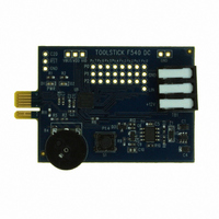
TOOLSTICK540DC
Description
DAUGHTER CARD TOOLSTICK F540
Manufacturer
Silicon Laboratories Inc
Series
ToolStickr
Type
MCUr
Datasheets
1.TOOLSTICK540DC.pdf
(274 pages)
2.TOOLSTICK540DC.pdf
(16 pages)
3.TOOLSTICK540DC.pdf
(12 pages)
Specifications of TOOLSTICK540DC
Contents
Daughter Card
Processor To Be Evaluated
C8051F54x
Processor Series
C8051F54x
Interface Type
USB
Operating Supply Voltage
2.7 V to 3.6 V
Lead Free Status / RoHS Status
Lead free / RoHS Compliant
For Use With/related Products
C8051F54x
For Use With
336-1345 - TOOLSTICK BASE ADAPTER336-1182 - ADAPTER USB DEBUG FOR C8051FXXX
Lead Free Status / Rohs Status
Lead free / RoHS Compliant
Other names
336-1717


24.3.1. Edge-triggered Capture Mode
In this mode, a valid transition on the CEXn pin causes the PCA to capture the value of the PCA coun-
ter/timer and load it into the corresponding module's 16-bit capture/compare register (PCA0CPLn and
PCA0CPHn). The CAPPn and CAPNn bits in the PCA0CPMn register are used to select the type of transi-
tion that triggers the capture: low-to-high transition (positive edge), high-to-low transition (negative edge),
or either transition (positive or negative edge). When a capture occurs, the Capture/Compare Flag (CCFn)
in PCA0CN is set to logic 1. An interrupt request is generated if the CCFn interrupt for that module is
enabled. The CCFn bit is not automatically cleared by hardware when the CPU vectors to the interrupt ser-
vice routine, and must be cleared by software. If both CAPPn and CAPNn bits are set to logic 1, then the
state of the Port pin associated with CEXn can be read directly to determine whether a rising-edge or fall-
ing-edge caused the capture.
Bit Number
Capture triggered by positive edge on CEXn
Capture triggered by negative edge on CEXn
Capture triggered by any transition on CEXn
Software Timer
High Speed Output
Frequency Output
8-Bit Pulse Width Modulator (Note 7)
9-Bit Pulse Width Modulator (Note 7)
10-Bit Pulse Width Modulator (Note 7)
11-Bit Pulse Width Modulator (Note 7)
16-Bit Pulse Width Modulator
Notes:
1. X = Don’t Care (no functional difference for individual module if 1 or 0).
2. A = 1 to enable interrupts for this module (PCA interrupt triggered on CCFn set to 1).
3. B = 1 to enable 8th, 9th, 10th or 11th bit overflow interrupt (Depends on setting of CLSEL[1:0]).
4. C = When set to 0, the digital comparator is off. For high speed and frequency output modes, the
5. D = Selects whether the Capture/Compare register (0) or the Auto-Reload register (1) for the associated
6. E = When set to 1, a match event will cause the CCFn flag for the associated channel to be set.
7. All modules set to 8, 9, 10 or 11-bit PWM mode use the same cycle length setting.
associated pin will not toggle. In any of the PWM modes, this generates a 0% duty cycle (output = 0).
channel is accessed via addresses PCA0CPHn and PCA0CPLn.
Operational Mode
Table 24.2. PCA0CPM and PCA0PWM Bit Settings for
PCA Capture/Compare Modules
Rev. 1.1
X X 1 0 0 0 0 A 0 X B XXX
X X 0 1 0 0 0 A 0 X B XXX
X X 1 1 0 0 0 A 0 X B XXX
X C 0 0 1 0 0 A 0 X B XXX
X C 0 0 1 1 0 A 0 X B XXX
X C 0 0 0 1 1 A 0 X B XXX
7 6 5 4 3 2 1 0 7 6 5
0 C 0 0 E 0 1 A 0 X B XXX
0 C 0 0 E 0 1 A D X B XXX
0 C 0 0 E 0 1 A D X B XXX
0 C 0 0 E 0 1 A D X B XXX
1 C 0 0 E 0 1 A 0 X B XXX
PCA0CPMn
C8051F54x
PCA0PWM
4–2 1–0
XX
XX
XX
XX
XX
XX
XX
00
01
10
11
253
Related parts for TOOLSTICK540DC
Image
Part Number
Description
Manufacturer
Datasheet
Request
R

Part Number:
Description:
KIT TOOL EVAL SYS IN A USB STICK
Manufacturer:
Silicon Laboratories Inc
Datasheet:

Part Number:
Description:
TOOLSTICK DEBUG ADAPTER
Manufacturer:
Silicon Laboratories Inc
Datasheet:

Part Number:
Description:
TOOLSTICK BASE ADAPTER
Manufacturer:
Silicon Laboratories Inc
Datasheet:

Part Number:
Description:
TOOLSTICK DAUGHTER CARD
Manufacturer:
Silicon Laboratories Inc
Datasheet:

Part Number:
Description:
TOOLSTICK DAUGHTER CARD
Manufacturer:
Silicon Laboratories Inc
Datasheet:

Part Number:
Description:
TOOLSTICK DAUGHTER CARD
Manufacturer:
Silicon Laboratories Inc
Datasheet:

Part Number:
Description:
TOOLSTICK PROGRAMMING ADAPTER
Manufacturer:
Silicon Laboratories Inc
Datasheet:

Part Number:
Description:
TOOLSTICK DAUGHTER CARD
Manufacturer:
Silicon Laboratories Inc
Datasheet:

Part Number:
Description:
KIT STARTER TOOLSTICK
Manufacturer:
Silicon Laboratories Inc
Datasheet:

Part Number:
Description:
KIT UNIVERSITY TOOLSTICK STARTER
Manufacturer:
Silicon Laboratories Inc
Datasheet:

Part Number:
Description:
DAUGHTER CARD TOOLSTICK F330
Manufacturer:
Silicon Laboratories Inc
Datasheet:

Part Number:
Description:
CARD DAUGHTER UNIVRSTY TOOLSTICK
Manufacturer:
Silicon Laboratories Inc
Datasheet:

Part Number:
Description:
DAUGHTER CARD TOOLSTICK F582
Manufacturer:
Silicon Laboratories Inc
Datasheet:

Part Number:
Description:
DAUGHTER CARD TOOLSTICK F500
Manufacturer:
Silicon Laboratories Inc
Datasheet:

Part Number:
Description:
DAUGHTER CARD TOOLSTICK F560
Manufacturer:
Silicon Laboratories Inc
Datasheet: