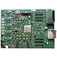
HW-V5-ML550-UNI-G Xilinx Inc, HW-V5-ML550-UNI-G Datasheet - Page 29

HW-V5-ML550-UNI-G
Manufacturer Part Number
HW-V5-ML550-UNI-G
Description
EVALUATION PLATFORM VIRTEX-5
Manufacturer
Xilinx Inc
Series
Virtex™-5 LXTr
Type
FPGAr
Datasheet
1.HW-V5-ML550-UNI-G.pdf
(88 pages)
Specifications of HW-V5-ML550-UNI-G
Contents
Development Platform, Power Supply, Loopback Board, CompactFlash Card, software and documentation
Silicon Manufacturer
Xilinx
Features
64M X 8 DDR SDRAM Memory, Six Samtec LVDS Connectors
Kit Contents
Board, Cable, PSU, CD, Docs
Silicon Family Name
Virtex-5
Silicon Core Number
XC5VLX50T-FFG1136
Rohs Compliant
Yes
Lead Free Status / RoHS Status
Lead free / RoHS Compliant
For Use With/related Products
Virtex™-5 LXT
Lead Free Status / RoHS Status
Lead free / RoHS Compliant, Lead free / RoHS Compliant
Available stocks
Company
Part Number
Manufacturer
Quantity
Price
Voltage Regulators (TI PTH05000)
ML550 Networking Interfaces Platform
UG202 (v1.4) April 18, 2008
5V DC @6A
LVDS Loopback Board (Xilinx P/N 0431395)
Voltage Regulator ±5% Margin Adjustment (in 2.5% Increments)
Converter
AC to DC
R
outputs a halved frequency on pins U17.12 and U17.11, DIVCLK_P and DIVCLK_N
respectively. As previously mentioned, these output pins are connected to the FPGA.
LVDS transmit to receive loopback can be achieved with either the LVDS Loopback board
included in the kit, or with the Precision Interconnect Blue Ribbon Cables (Xilinx P/N
HW-LVDS-CBL-80, order separately).
LVDS Loopback Board details.
Figure 3-7
various on-board voltage sources. As shown in
5.0V voltage to the board. This voltage source is provided to all on-board regulators to
generate the 1.0V, 2.5V, and 3.3V voltages for the digital section of the board. All Bank
V
Onboard digital voltages are as follows:
The regulators shown in
the FPGA, or they can be enabled or inhibited through the use of on-board jumpers. The
jumpers use the following conventions:
CCO
Figure 3-7: Block Diagram of the Five Voltage Regulators
1.0V V
2.5V V
2.5V V
2.5V System (VR3)
3.3V System (VR1)
Regulator
System
voltages are 2.5V.
3.3V
3.3V
2.1 mm
Barrel
Plug
VR1
shows the voltage regulators used on ML550 Development Board to provide
CCINT
CCAUX
CCO
(VR4)
(VR2)
(VR5)
J20
Regulator
System
2.5V
2.5V
Table 3-9
www.xilinx.com
VR3
can have their outputs controlled over a ±5% range by
On/Off
Regulator
SW8
Appendix B, “LVDS Loopback Board”
V
2.5V
2.5V
CCO
VR4
Figure
3 Amp
Fuse
F1
3-7, connector J20 provides the main
Regulator
Voltage Regulators (TI PTH05000)
V
CCAUX
2.5V
2.5V
VR5
5V
UG202_3_07_120706
Regulator
V
CCINT
1.0V
1.0V
VR2
includes
29


