HW-V5-ML550-UNI-G Xilinx Inc, HW-V5-ML550-UNI-G Datasheet - Page 75
HW-V5-ML550-UNI-G
Manufacturer Part Number
HW-V5-ML550-UNI-G
Description
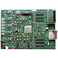
EVALUATION PLATFORM VIRTEX-5
Manufacturer
Xilinx Inc
Series
Virtex™-5 LXTr
Type
FPGAr
Datasheet
1.HW-V5-ML550-UNI-G.pdf
(88 pages)
Specifications of HW-V5-ML550-UNI-G
Contents
Development Platform, Power Supply, Loopback Board, CompactFlash Card, software and documentation
Silicon Manufacturer
Xilinx
Features
64M X 8 DDR SDRAM Memory, Six Samtec LVDS Connectors
Kit Contents
Board, Cable, PSU, CD, Docs
Silicon Family Name
Virtex-5
Silicon Core Number
XC5VLX50T-FFG1136
Rohs Compliant
Yes
Lead Free Status / RoHS Status
Lead free / RoHS Compliant
For Use With/related Products
Virtex™-5 LXT
Lead Free Status / RoHS Status
Lead free / RoHS Compliant, Lead free / RoHS Compliant
Available stocks
Company
Part Number
Manufacturer
Quantity
Price


ML550 Networking Interfaces Platform
UG202 (v1.4) April 18, 2008
R
Once configured, these settings normally are not changed.
The following steps are performed next:
Table C-5: Resistor Value Settings
Table C-6: Reference Voltage Parameters
At startup of the LCD controller (after RESETB operation), the resistor and reference
voltage values are:
The Resistor selection value MUST be set to 101b when using this LCD panel.
After the display is brought to operational mode, it is best to wait at least 1 ms to ensure the
stabilization of power supply levels. After this time, all other necessary display
initializations can be performed.
SV5
1+(Rb/Ra)
0
0
..
..
1
1
Select the LCD bias settings.
Start the onboard converter, regulator, and follower
Set the Regulator Resistor values (see
Configure the reference voltage register parameters (see
Resistor selection is: 0,0,0
Reference voltage is: 1,0,0,0,0,0
When SHL is set to 1, the common lines are scanned in opposite direction.
The duty cycle is selected as 1/65 by hardwiring the controller IC pads on the
display PCB.
The LCD bias is set to:
-
-
SV4
0
0
..
..
1
1
1/7: when the BIAS bit is 0
1/9: when the BIAS bit is 1
1.90
SV3
000
…
0
0
..
1
1
SV2
2.19
001
www.xilinx.com
0
0
..
..
1
1
3-Bit Data Settings (R2 R1 R0)
SV1
2.55
010
0
0
..
..
1
1
SV0
3.02
011
0
1
..
..
0
1
Table
C-5)
3.61
100
Reference Voltage Parameter ( )
4.35
101
Hardware Schematic Diagram
Table
5.29
110
62
63
C-6)
0
1
..
..
6.48
111
75
Related parts for HW-V5-ML550-UNI-G
Image
Part Number
Description
Manufacturer
Datasheet
Request
R

Part Number:
Description:
IC CPLD .8K 36MCELL 44-VQFP
Manufacturer:
Xilinx Inc
Datasheet:

Part Number:
Description:
IC CPLD 72MCRCELL 10NS 44VQFP
Manufacturer:
Xilinx Inc
Datasheet:

Part Number:
Description:
IC CPLD 1.6K 72MCELL 64-VQFP
Manufacturer:
Xilinx Inc
Datasheet:

Part Number:
Description:
IC CR-II CPLD 64MCELL 44-VQFP
Manufacturer:
Xilinx Inc
Datasheet:

Part Number:
Description:
IC CPLD 1.6K 72MCELL 100-TQFP
Manufacturer:
Xilinx Inc
Datasheet:

Part Number:
Description:
IC CR-II CPLD 64MCELL 56-BGA
Manufacturer:
Xilinx Inc
Datasheet:

Part Number:
Description:
IC CPLD 72MCRCELL 7.5NS 44VQFP
Manufacturer:
Xilinx Inc
Datasheet:
Part Number:
Description:
IC CR-II CPLD 64MCELL 100-VQFP
Manufacturer:
Xilinx Inc
Datasheet:
Part Number:
Description:
IC CPLD 1.6K 72MCELL 100-TQFP
Manufacturer:
Xilinx Inc
Datasheet:

Part Number:
Description:
IC CPLD 72MCRCELL 7.5NS 64VQFP
Manufacturer:
Xilinx Inc
Datasheet:
Part Number:
Description:
IC CPLD 1.6K 72MCELL 100-TQFP
Manufacturer:
Xilinx Inc
Datasheet:

Part Number:
Description:
IC CPLD 1.5K 64MCELL HP 44-VQFP
Manufacturer:
Xilinx Inc

Part Number:
Description:
IC CPLD 36MCRCELL 15NS 44PLCC
Manufacturer:
Xilinx Inc
Datasheet:

Part Number:
Description:
IC CPLD 36MCRCELL 10NS 44PLCC
Manufacturer:
Xilinx Inc
Datasheet:

Part Number:
Description:
IC CPLD 1.5K 64MCELL HP 44-VQFP
Manufacturer:
Xilinx Inc