HW-V5-ML550-UNI-G Xilinx Inc, HW-V5-ML550-UNI-G Datasheet - Page 43
HW-V5-ML550-UNI-G
Manufacturer Part Number
HW-V5-ML550-UNI-G
Description
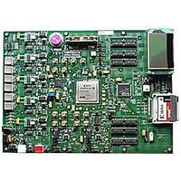
EVALUATION PLATFORM VIRTEX-5
Manufacturer
Xilinx Inc
Series
Virtex™-5 LXTr
Type
FPGAr
Datasheet
1.HW-V5-ML550-UNI-G.pdf
(88 pages)
Specifications of HW-V5-ML550-UNI-G
Contents
Development Platform, Power Supply, Loopback Board, CompactFlash Card, software and documentation
Silicon Manufacturer
Xilinx
Features
64M X 8 DDR SDRAM Memory, Six Samtec LVDS Connectors
Kit Contents
Board, Cable, PSU, CD, Docs
Silicon Family Name
Virtex-5
Silicon Core Number
XC5VLX50T-FFG1136
Rohs Compliant
Yes
Lead Free Status / RoHS Status
Lead free / RoHS Compliant
For Use With/related Products
Virtex™-5 LXT
Lead Free Status / RoHS Status
Lead free / RoHS Compliant, Lead free / RoHS Compliant
Available stocks
Company
Part Number
Manufacturer
Quantity
Price


ML550 Networking Interfaces Platform
UG202 (v1.4) April 18, 2008
Power Monitor Circuitry
R
The ML550 hosts a 2 x 13 0.1-inch male header connector which provides test points for the
ML550 power regulators as shown in
Table 3-16: Power Monitor Connector P72 Pinout
The regulator outputs are connected to a series Kelvin resistor, which is then connected to
the target power plane. ML550 voltage regulator topology is discussed in detail in sections
“Voltage Regulators (TI PTH05000),” page 29
summary of the regulator connections to P72 is given in
Note:
Pin #
10
12
13
14
15
16
17
18
19
20
21
22
23
24
25
26
11
1
2
3
4
5
6
7
8
9
As indicated in Note 3 beneath
VCC2V5_VCCO_MON
VCC2V5_VAUX_MON
VCC1V0_VINT_MON
VCC3V3_SYS_MON
VCC2V5_VCCO_S+
VCC2V5_VAUX_S+
VCC2V5_VCCO_S–
VCC2V5_VAUX_S–
VCC1V0_VINT_S+
VCC1V0_VINT_S–
VCC3V3_SYS_S+
VCC3V3_SYS_S–
VCC2V5_MON
Signal Name
VCC5_MON
VCC2V5_S+
VCC2V5_S–
VCC5_S+
VCC5_S–
VCC5
Dgnd
Dgnd
Dgnd
Dgnd
NC
NC
NC
www.xilinx.com
ML550 System Monitor and Power Monitor Support
Table
Table
R
KELVIN
3-12, the S+ and S– pins of P72 are reversed.
R386
R386
R386
R384
R384
R384
R385
R385
R385
R383
R383
R383
R387
R387
R387
R201
R201
R201
3-16.
and
REF
“Power Monitor Connector,” page
Table 3-12, page
Schematic
20, 23
20, 23
20, 23
20, 24
20, 24
20, 24
20, 22
20, 22
20, 22
20, 22
20, 22
20, 22
20, 24
20, 24
20, 24
19, 20
19,20
19,20
19,20
20
20
20
20
20
20
20
33.
S– actual
S+ actual
S– actual
S+ actual
S– actual
S+ actual
S– actual
S+ actual
S– actual
S+ actual
S– actual
S+ actual
Notes
32. A
43
Related parts for HW-V5-ML550-UNI-G
Image
Part Number
Description
Manufacturer
Datasheet
Request
R

Part Number:
Description:
IC CPLD .8K 36MCELL 44-VQFP
Manufacturer:
Xilinx Inc
Datasheet:

Part Number:
Description:
IC CPLD 72MCRCELL 10NS 44VQFP
Manufacturer:
Xilinx Inc
Datasheet:

Part Number:
Description:
IC CPLD 1.6K 72MCELL 64-VQFP
Manufacturer:
Xilinx Inc
Datasheet:

Part Number:
Description:
IC CR-II CPLD 64MCELL 44-VQFP
Manufacturer:
Xilinx Inc
Datasheet:

Part Number:
Description:
IC CPLD 1.6K 72MCELL 100-TQFP
Manufacturer:
Xilinx Inc
Datasheet:

Part Number:
Description:
IC CR-II CPLD 64MCELL 56-BGA
Manufacturer:
Xilinx Inc
Datasheet:

Part Number:
Description:
IC CPLD 72MCRCELL 7.5NS 44VQFP
Manufacturer:
Xilinx Inc
Datasheet:
Part Number:
Description:
IC CR-II CPLD 64MCELL 100-VQFP
Manufacturer:
Xilinx Inc
Datasheet:
Part Number:
Description:
IC CPLD 1.6K 72MCELL 100-TQFP
Manufacturer:
Xilinx Inc
Datasheet:

Part Number:
Description:
IC CPLD 72MCRCELL 7.5NS 64VQFP
Manufacturer:
Xilinx Inc
Datasheet:
Part Number:
Description:
IC CPLD 1.6K 72MCELL 100-TQFP
Manufacturer:
Xilinx Inc
Datasheet:

Part Number:
Description:
IC CPLD 1.5K 64MCELL HP 44-VQFP
Manufacturer:
Xilinx Inc

Part Number:
Description:
IC CPLD 36MCRCELL 15NS 44PLCC
Manufacturer:
Xilinx Inc
Datasheet:

Part Number:
Description:
IC CPLD 36MCRCELL 10NS 44PLCC
Manufacturer:
Xilinx Inc
Datasheet:

Part Number:
Description:
IC CPLD 1.5K 64MCELL HP 44-VQFP
Manufacturer:
Xilinx Inc