EVAL-ADUC814QS Analog Devices Inc, EVAL-ADUC814QS Datasheet - Page 31
EVAL-ADUC814QS
Manufacturer Part Number
EVAL-ADUC814QS
Description
KIT DEV FOR ADUC814 QUICK START
Manufacturer
Analog Devices Inc
Series
QuickStart™ Kitr
Type
8052-corer
Datasheet
1.EVAL-ADUC814QSZ.pdf
(72 pages)
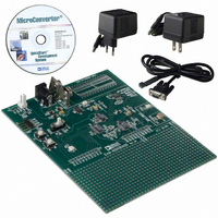
Specifications of EVAL-ADUC814QS
Contents
Evaluation Board, Power Supply, Cable, Software and Documentation
For Use With/related Products
ADuC814
Lead Free Status / RoHS Status
Contains lead / RoHS non-compliant


USING FLASH/EE PROGRAM MEMORY
The Flash/EE program memory array can be programmed in
one of two modes: serial downloading and parallel
programming.
Serial Downloading (In-Circuit Programming)
As part of its factory boot code, the ADuC814 facilitates code
download via the standard UART serial port. Serial download
mode is automatically entered on power-up or during a
hardware RESET operation if the external DLOAD pin is pulled
high through an external resistor, as shown in Figure 34. Once
in this mode, the user can download code to the program
memory array while the device is sited in its target application
hardware. A PC serial download executable is provided as part
of the ADuC814 QuickStart development system. The Serial
Download protocol is detailed in a MicroConverter Applications
Note uC004 available from the ADI MicroConverter website at
www.analog.com/microconverter.
Parallel Programming
The parallel programming mode is fully compatible with
conventional third-party Flash or EEPROM device program-
mers. A block diagram of the external pin configuration
required to support parallel programming is shown in Figure 35.
The high voltage (12 V) supply required for Flash/EE
programming is generated using on-chip charge pumps to
supply the high voltage program lines.
Figure 34. Flash/EE Memory Serial Download Mode Programming
ADuC814
DLOAD
DVDD
1kΩ
PULL DLOAD HIGH VIA
1kΩ RESISTOR DURING
RESET TO CONFIGURE
THE ADuC814 FOR
SERIAL DOWNLOAD MODE
Rev. A | Page 31 of 72
FLASH/EE PROGRAM MEMORY SECURITY
The ADuC814 facilitates three modes of Flash/EE program
memory security, which are described in the following sections.
These modes can be independently activated, restricting access
to the internal code space. These security modes can be enabled
as part of the user interface available on all ADuC814 serial or
parallel programming tools referenced on the MicroConverter
website at www.analog.com/microconverter.
Lock Mode
This mode locks code in memory, disabling parallel program-
ming of the program memory, although reading the memory in
parallel mode is still allowed. This mode is deactivated by
initiating a CODE-ERASE command in serial download or
parallel programming modes.
Secure Mode
This mode locks code in memory, disabling parallel program-
ming (program and VERIFY/READ commands). This mode is
deactivated by initiating a CODE-ERASE command in serial
download or parallel programming modes.
Serial Safe Mode
This mode disables serial download capability on the device. If
serial safe mode is activated and an attempt is made to reset the
part into serial download mode, i.e., RESET asserted and de-
asserted with DLOAD high, the part interprets the serial
download reset as a normal reset only. It therefore does not
enter serial download mode but only executes a normal reset
sequence. Serial safe mode can be disabled only by initiating a
CODE-ERASE command in parallel programming mode.
COMMAND
TIMING
Figure 35. Flash/EE Memory Parallel Programming
5V
V
GND
P1.1–P1.4
P1.5–P1.7
DD
ADuC814
DLOAD
RESET
P1.0
P3
DATA
GND
V
ENABLE
ADuC814
DD
Related parts for EVAL-ADUC814QS
Image
Part Number
Description
Manufacturer
Datasheet
Request
R


Part Number:
Description:
BOARD EVAL FOR SI270X-A
Manufacturer:
Silicon Laboratories Inc
Datasheet:

Part Number:
Description:
BUCK CONV REF DESIGN KIT IP1201
Manufacturer:
International Rectifier
Datasheet:
Part Number:
Description:
BOARD DEMO SYNC DUAL BUCK CNVTER
Manufacturer:
International Rectifier
Datasheet:
Part Number:
Description:
BOARD DEMO SYNC BUCK CONVETER
Manufacturer:
International Rectifier
Datasheet:

Part Number:
Description:
EVALBOARD/EB Omnidirectional microphone - Analog
Manufacturer:
Analog Devices
Datasheet:
Part Number:
Description:
EVALBOARD/EB Omnidirectional microphone - Analog
Manufacturer:
Analog Devices
Datasheet:


Part Number:
Description:
BOARD EVAL LED DRIVER LT3756
Manufacturer:
Linear Technology
Datasheet:

Part Number:
Description:
BOARD EVAL FOR AD7741/7742
Manufacturer:
Analog Devices Inc
Datasheet:

Part Number:
Description:
±1.7g Dual-Axis IMEMS Accelerometer Evaluation Board
Manufacturer:
Analog Devices Inc
Datasheet:

Part Number:
Description:
IC MULTIPLIER ANALOG 8-SOIC T/R
Manufacturer:
Analog Devices Inc
Datasheet:

Part Number:
Description:
IC ANALOG MULTIPLIER 8-DIP
Manufacturer:
Analog Devices Inc
Datasheet:
Part Number:
Description:
IC ANALOG MULTIPLIER 8-SOIC
Manufacturer:
Analog Devices Inc
Datasheet:
Part Number:
Description:
IC ANALOG MULTIPLIER 8-DIP
Manufacturer:
Analog Devices Inc
Datasheet: