1249B B&K Precision, 1249B Datasheet
1249B
Specifications of 1249B


1249B Summary of contents
Page 1
... INSTRUCTION MANUAL Model 1249B NTSC GENERATOR ...
Page 2
... TEST INSTRUMENT SAFETY Normal use of test equipment exposes you to a certain amount of danger from electrical shock because testing must sometimes be performed where exposed voltage is present. An electrical shock causing 10 milliamps of current to pass through the heart will stop most human heartbeats. Voltage as low as 35 volts rms should be considered dangerous and hazardous since it can produce a lethal current under certain conditions ...
Page 3
TEST INSTRUMENT SAFETY ............................. inside front cover INTRODUCTION ........................................................................4 FEATURES .......................................................................................... 5 SPECIFICATIONS .............................................................................. 6 DEFINITIONS OF TERMS ................................................................ 8 THE NTSC COLOR VIDEO SIGNAL ............................................ 11 History ......................................................................................... 11 Horizontal Sync ........................................................................... 11 Vertical Sync ............................................................................... 12 Amplitude .................................................................................... ...
Page 4
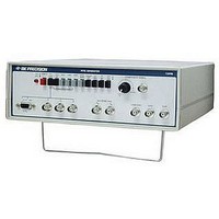
... INTRODUCTION T he B+K PRECISION Model 1249B NTSC Generator is a versatile, low cost, precision television/video generator. It generates a variety of test signals and patterns for comprehensive testing, servicing, and adjustment of video and television equipment. Its applications include television receivers, video tape recorders, closed circuit television ...
Page 5
FEATURES NTSC COLOR BARS Generates standard NTSC color bars pattern (eight bars of standard EIA colors) at NTSC prescribed luminance and chrominance levels and phase. SELECTABLE COLOR Color can be switched on or off. CONVERGENCE PATTERNS Dots, crosshatch, center dot, ...
Page 6
SPECIFICATIONS PATTERNS NTSC Color Bars: White (75% or I00%. switch selectable), yellow, cyan, green, magenta, red, blue, black (7.5% set-up). Chroma is switch selectable; COLOR OFF obtains stair case from color bars (stair case white level is switch selectable at ...
Page 7
SPECIFICATIONS (CONT.) SOUND SUBCARRIER 4.5MHz ±0.2% modulated by approximately 1KHz audio tone, switch selectable. SYNC OUTPUTS Composite: NTSC-M TTL level: negative interlaced scan for NTSC color bars, selectable ' interlaced or progressive scan for convergence patterns. Horizontal: TTL level (positive ...
Page 8
DEFINITIONS OF TERMS BARS Pattern. See “NTSC Color Bars”. Back Porch. The portion of a composite video signal between the trailing edge of the horizontal sync pulse and the end of the horizontal blanking pedestal. The color burst occurs during ...
Page 9
DEFINITIONS OF TERMS (CONT.) Field. One-half a television picture. One complete vertical scan of the picture containing 262.5 lines. Two fields make up a complete television picture (frame). The lines of Field 1 are vertically interlaced with Field 2 for ...
Page 10
DEFINITIONS OF TERMS (CONT.) Resolution. See "Horizontal Resolution" and "Vertical Resolution". Saturation. Vividness of color. Degree to which a color is not diluted by white light. Highly saturated color is very vivid. The same hue becomes a pastel shade when ...
Page 11
THE NTSC COLOR VIDEO SIGNAL Fig. 1. Composite of Video Signal; One Horizontal Line of NTSC Color Bars Signal HISTORY In 1953, the NTSC (National Television Systems Committee) established the color television standards now in use by the television broadcast ...
Page 12
THE NTSC COLOR VIDEO SIGNAL (CONT.) horizontal sync pulse at the -40 IEEE units level. An explanation of IEEE units follows in the "Amplitude" paragraph. When the horizontal sync pulse is detected in a television receiver, it initiates flyback, which ...
Page 13
THE NTSC COLOR VIDEO SIGNAL (CONT.) Fig. 2A. Compo site Video Signal Showing Vertical Blanking Interval (Field 1). 13 ...
Page 14
THE NTSC COLOR VIDEO SIGNAL (CONT.) Fig. 2B. Composite Video Signal Showing Vertical Blanking Interval (Field 2) 14 ...
Page 15
THE NTSC COLOR VIDEO SIGNAL (CONT.) white. Levels between +7.5 and +100 units produce various shadings of grey. Even when a composite video signal is not at the 1 volt peak-to-peak level, the ratio between the sync pulse and video ...
Page 16
THE NTSC COLOR VIDEO SIGNAL (CONT.) Fig. 3. Elements of Color Television Signal 16 ...
Page 17
THE NTSC COLOR VIDEO SIGNAL (CONT.) (saturation) set forth by the NTSC. This is the test signal used in broadcasting studios and transmitting equipment. This makes the NTSC Generator a superior instrument for servicing and adjusting color television receivers and ...
Page 18
CONTROLS AND INDICATORS 1. POWER Switch. Turns power on and off. 2. RGB TTL/LOW Switch. Selects TTL or low RGB output level. When this switch is released (LOW position), a positive logic state at the RGB output jacks (R, G, ...
Page 19
CONTROLS AND INDICATORS (CONT.) approximately 1KHz) is included in the signal at the IF/RF output jack. When this switch is disengaged, no sound carrier is included in the signal. 9. IF/RF Switch. Sets modulated output signal (at the IF/RF output ...
Page 20
CONTROLS AND INDICATORS (CONT.) Fig. 4. Controls and Indicators 20 ...
Page 21
CONTROLS AND INDICATORS (CONT.) 19. G Jack. Provides green output signal for use with RGB Ω monitors. Output impedance is 75 switch selectable (using the RGB TTL/LOW switch). 20. R Jack. Provides red output signal for use with RGB monitors. ...
Page 22
OPERATING INSTRUCTIONS WARNING To prevent electrical shock, observe the precautions listed in INSTRUMENT SAFETY section, located on the inside front cover of this manual. PRECAUTION AND TIPS 1. The most commonly encountered hazard in the use of this instrument is ...
Page 23
OPERATING INSTRUCTIONS (CONT Output The rf output of the NTSC Generator may be applied to a television receiver, video tape recorder or other video equipment tunable to channel Use the following procedure: a. Connect a ...
Page 24
OPERATING INSTRUCTIONS (CONT calibrated 1Vp-p signal level with negative sync polarity is available when the COMPOSITE VIDEO LEVEL control is fully counterclockwise to the CAL position. d. Patterns may now be selected. NTSC STANDARD COLOR BAR PATTERN 1. ...
Page 25
... Such color monitors are often used with computers having color graphic display capability, etc. The Model 1249B will provide compatible test signals for most RGB monitors using standard 525 line, 15.750KHz horizontal 25 ...
Page 26
... RGB signals and vary color saturation in response to analog changes of the signal level. Others use higher TTL level excitation and display only fully saturated colors- The Model 1249B NTSC Generator provides signals for most versions. Separate R, G, and B outputs with selectable TTL or LOW level are available at BNC connectors on the front panel ...
Page 27
OPERATING INSTRUCTIONS (CONT.) 2. Connect another cable from the COMP SYNC output jack to the external trigger input of the oscilloscope. 3. Select the external triggering mode on the oscilloscope sweep rate of about 10µs/div is appropriate for ...
Page 28
APPLICATIONS NTSC COLOR BARS Versatility The NTSC color bars pattern is the basic pattern used for most testing, troubleshooting and adjustments in video equipment one of the most valuable and versatile color patterns ever devised. The NTSC color ...
Page 29
APPLICATIONS (CONT.) may be exam-fined throughout the VCR for proper luminance to chroma proportions. Another problem that may be encountered is a difference in delay between the luminance signal and the chroma signal. This will cause fuzziness along the edges ...
Page 30
APPLICATIONS (CONT.) SYNC The NTSC color bars and staircase pattern include NTSC sync pulses, the same type as those produced by a broadcast station. The sync amplitude of 40 IEEE units is often the reference against which the remainder of ...
Page 31
APPLICATIONS (CONT.) MATV APPLICATIONS Master antenna systems for hotels, motels, apartment buildings, etc. can be checked by applying the channel output of the Generator to the input of the network (or a branch of the network) ...
Page 32
APPLICATIONS (CONT.) d. The display shape depends upon the chroma bandpass, demodulator alignment, and design of the TV chassis. The better the alignment and bandwidth, the closer the vector waveform will be to the ideal waveform. e. Display shape will ...
Page 33
APPLICATIONS CONT.) Fig. 7. Typical Vectorscope Display of Demodulated Color Bars Pattern Viewed on Conventional Oscilloscope. 33 ...
Page 34
... Fig. 8. Keep in mind that some calibration procedures require high precision test instruments. Those adjustments should be attempted only if the proper test equipment is available and you are experienced in its use. The following test equipment is required for complete calibration: • NTSC Vectorscope. • ...
Page 35
MAINTENANCE (CONT.) R7 Fig. 8. Adjustment and Test Point Locations. 35 ...
Page 36
MAINTENANCE (CONT.) 3. Connect the Waveform Monitor and the Vectorscope to the COMPOSITE VIDEO jack (terminated into 75 S2). Set the Waveform Monitor response to FLAT and the sweep to 2H. Set the variable amplitude control on the Waveform Monitor ...
Page 37
... Press the NTSC BARS switch and release the COLOR OFF switch. Set the Waveform Monitor for a sweep speed of 1µs/div. 3. Adjust VR10 and VR11 on the 1249B for minimum ripple on the bottom edge of the sync pulse. Repeat until no further improvement is possible. Color Adjustments 1 ...
Page 38
Warranty Service: Please return the product in the original packaging with proof of purchase to the address below. Clearly state in writing the performance problem and return any leads, probes, connectors and accessories that you are using with the device. ...
Page 39
B&K Precision Corp. warrants to the original purchaser that its products and the component parts thereof, will be free from defects in workmanship and materials for a period of one year from date of purchase. B&K Precision Corp. will, without ...
Page 40
... For connection to any other point, an isolation transformer is needed. 9. Capacitive coupled outputs of the Model 1249B NTSC Generator are rated at ±35 volts ( peak) maximum: this includes the IF/RF and COMPOSITE VIDEO jack. All other input and output jacks are direct coupled and are rated at ±5 volts ( peak) maximum ...
Page 41
Printed in USA 22820 Savi Ranch Parkway Yorba Linda, CA 92887 www.bkprecision.com © 2006 B&K Precision Corp. 41 PN# 480-760-9-001 ...