1249B B&K Precision, 1249B Datasheet - Page 29
1249B
Manufacturer Part Number
1249B
Description
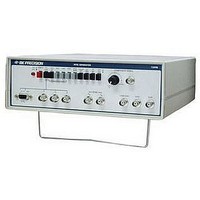
COLOR GENERATORNTSC/RGB
Manufacturer
B&K Precision
Type
NTSC Benchtopr
Specifications of 1249B
Patterns
Bar, Dot, Crosshatch, Raster
Connection Method
RCA, RF, S-Video
Power Source
105,130VAC
Signal Generator Type
NTSC Pattern
Supply Voltage Range
105V To 130V
External Height
86mm
External Width
290mm
External Depth
264mm
Frequency
30 Hz
Equipment Type
NTSC Pattern Generators
Lead Free Status / RoHS Status
na
Lead Free Status / RoHS Status
na
Other names
BK1249B


may be exam-fined throughout the VCR for proper luminance
to chroma proportions. Another problem that may be
encountered is a difference in delay between the luminance
signal and the chroma signal. This will cause fuzziness along
the edges of the color bars.
STAIRCASE
switches engaged) is recommended for frequency equalization
adjustment in the recorder amplifier circuit of VCR's. The FM
signal which carries luminance information in a VCR is shifted
to a different frequency with each step of the staircase signal.
However, record current should remain constant across the FM
frequency band. Frequency equalization should be adjusted so
that record current is equal for all steps of the staircase input
signal.
CONVERGENCE
Center Cross Pattern
switch disengaged) should intersect at the center of the screen
and there should be no tilt of the horizontal line. Improper
centering indicates the need for centering adjustment or a
deflection circuit fault. Tilt may require repositioning of the
deflection yoke for correction. This pattern also provides a
good general check of vertical and horizontal sync.
Center Dot Pattern
Some technicians and engineers prefer to use a center dot for
centering adjustment.
The staircase pattern (NTSC BARS and COLOR OFF
The center cross pattern (LINE switch engaged. 7 X 11
APPLICATIONS (CONT.)
29
Dots Pattern
is used for static convergence, usually by converging the
center dot of the pattern. A 7 x I 1 dot pattern is generated.
Most sets have some overscan so that all dots are not visible,
except possible under low voltage conditions. Some sets have
a tendency toward more overscan than others. It is desirable to
display at least a 7 x 9 dot pattern.
Crosshatch Pattern
engaged) is normally preferred for dynamic convergence,
although some technicians prefer the dots pattern for both
static and dynamic convergence. The crosshatch pattern
checks vertical and horizontal linearity. Each square should be
the same size which is a convenient reference for making
linearity adjustments. The crosshatch pattern is also used to
check pincushion distortion which often appears at the outside
ed
RF and I-F
receivers are essentially the same. Servicing of these sections
can be aided by the rf and i-f outputs of the NTSC Generator.
Performance of the VCR or TV set should be nearly as good
when using the rf signal on channel 3 or 4 as when applying
composite video directly into the video section. If not, there is
a problem in the tuner or i-f section which can be isolated by
injecting rf or i-f signals at various points and identifying the
point at which normal operation is lost.
The dots pattern (DOT and 7 X 11 switches both engaged)
The crosshatch pattern (LINE and 7 X 11 switches both
The tuners and i-f sections of VCR's and color television
g
es of large screen TV sets as bends in the lines.