1249B B&K Precision, 1249B Datasheet - Page 34
1249B
Manufacturer Part Number
1249B
Description
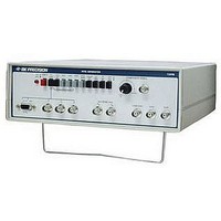
COLOR GENERATORNTSC/RGB
Manufacturer
B&K Precision
Type
NTSC Benchtopr
Specifications of 1249B
Patterns
Bar, Dot, Crosshatch, Raster
Connection Method
RCA, RF, S-Video
Power Source
105,130VAC
Signal Generator Type
NTSC Pattern
Supply Voltage Range
105V To 130V
External Height
86mm
External Width
290mm
External Depth
264mm
Frequency
30 Hz
Equipment Type
NTSC Pattern Generators
Lead Free Status / RoHS Status
na
Lead Free Status / RoHS Status
na
Other names
BK1249B


MAINTENANCE
CASE REMOVAL
case must be removed. To remove the case, perform the following
steps:
1.
2.
FUSE REPLACEMENT
If the fuse blows the pilot light will go out and the Generator will
not operate. The fuse should not open unless a problem has
In order to replace the fuse or calibrate the NTSC Generator the
Turn the Generator upside down and remove the four screws.
Lift the bottom half of the case straight up.
The following instructions are for use by
qualified service personnel only. To avoid
electrical shock, do not perform servicing
unless you are qualified to do so.
A shock hazard is present when the top cover
is removed if the power cord is plugged into
an ac outlet. AC line voltage may be present
on the fuse holder, line cord receptacle,
POWER switch, and power transformer
even when the POWER switch is off.
W ARNI N G
34
developed in the unit. Determine and correct the cause of the
blown fuse, then replace only with a 1/16A, 250V slow blow
fuse (B+K Precision Part No. 198-303-0-062). The fuse is
only accessible by removing the case. For fuse location refer
to Fig. 8.
CALIBRATION
factory prior to shipment. Readjustment is recommended
only if repairs have been made in a circuit affecting
calibration. The location of the calibration adjustments is
shown in Fig. 8. Keep in mind that some calibration
procedures require high precision test instruments. Those
adjustments should be attempted only if the proper test
equipment is available and you are experienced in its use.
The following test equipment is required for complete
calibration:
1.
2.
This unit was carefully checked and calibrated at the
•
•
•
Before beginning calibration, turn on the NTSC
Generator and allow 15 minutes of warm-up time.
Engage COLOR OFF and BAST switches. All other
switches (except POWER) should be disengaged.
NTSC Vectorscope.
Waveform Monitor.
Frequency Counter with l ppm time base accuracy.
B+K Precision Model 1856D or equivalent.