1249B B&K Precision, 1249B Datasheet - Page 31
1249B
Manufacturer Part Number
1249B
Description
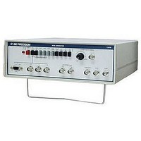
COLOR GENERATORNTSC/RGB
Manufacturer
B&K Precision
Type
NTSC Benchtopr
Specifications of 1249B
Patterns
Bar, Dot, Crosshatch, Raster
Connection Method
RCA, RF, S-Video
Power Source
105,130VAC
Signal Generator Type
NTSC Pattern
Supply Voltage Range
105V To 130V
External Height
86mm
External Width
290mm
External Depth
264mm
Frequency
30 Hz
Equipment Type
NTSC Pattern Generators
Lead Free Status / RoHS Status
na
Lead Free Status / RoHS Status
na
Other names
BK1249B


APPLICATIONS (CONT.)
MATV APPLICATIONS
buildings, etc. can be checked by applying the channel 3 or 4
rf output of the Generator to the input of the network (or a
branch of the network) and examining the pattern obtained
on channel 3 or 4 directly from the screen of each TV set.
To isolate problems in the distribution network from
problems in an individual TV set, apply the channel 3 or 4 rf
output of the NTSC Generator directly to the antenna
terminals of the TV set. A proper display on the screen
indicates that there is a problem in the distribution network.
VECTORSCOPE MEASUREMENTS
trouble analysis than observing the pattern displayed on the
picture tube. If an NTSC Vectorscope is available, it is
recommended. The display on an NTSC Vectorscope with
the NTSC color bars pattern applied should be six dots located
within the six small boxes of the Vectorscope as shown in Fig.
3. The displayed vector pattern may be extracted from
anywhere in the composite video or 3.58MHz color circuits.
Amplitude must be initially adjusted so the color burst aligns
with the 75% mark on the vectorscope graticule.
If an NTSC vectorscope is not available, the demodulated
color signals from the red and blue guns can be used as the
X and Y inputs to a good laboratory oscilloscope (such as the
B+K Precision Model 2120). The resulting display is a
vectorscope pattern as shown in Fig. 7. The oscilloscope
should be set up for vectorscope operation as follows:
Master antenna systems for hotels, motels, apartment
A vectorscope measurement is usually more helpful for
31
1.
2.
3.
4.
5.
6.
Select the NTSC BARS pattern and apply to the TV set
under test.
Set up to the oscilloscope for X-Y operation. Adjust the
position controls to center the dot on the screen with no
signal In
Connect the X and Y inputs of the oscilloscope to the red gun
as shown in Fig. 5.
Adjust the vertical and horizontal oscilloscope gain to equal
amounts. This will cause the spot to become a 45° line as
shown in Fig. 5.
Leave the vertical (Y) input connected to the red gun but
move the horizontal input to the blue gun as shown in Fig. 6.
A display similar to that shown in Fig. 7 should be obtained.
However, several factors may affect the display as follows:
a.
b.
The HUE control of the TV under test will rotate the
display. The HUE control may be adjusted to obtain the
display nearest to that shown in Fig. 7. Starting from a
centered position, the HUE control can typically rotate
the display ±30
The COLOR control of the TV under test (chroma
amplitude) adjusts the amplitude of the display. This
control should typically be adjusted for the highest
amplitude obtainable without distortion (just below the
point where further rotation of the control does not
increase amplitude of display).
p
ut to the oscilloscope.