1249B B&K Precision, 1249B Datasheet - Page 19
1249B
Manufacturer Part Number
1249B
Description
COLOR GENERATORNTSC/RGB
Manufacturer
B&K Precision
Type
NTSC Benchtopr
Specifications of 1249B
Patterns
Bar, Dot, Crosshatch, Raster
Connection Method
RCA, RF, S-Video
Power Source
105,130VAC
Signal Generator Type
NTSC Pattern
Supply Voltage Range
105V To 130V
External Height
86mm
External Width
290mm
External Depth
264mm
Frequency
30 Hz
Equipment Type
NTSC Pattern Generators
Lead Free Status / RoHS Status
na
Lead Free Status / RoHS Status
na
Other names
BK1249B


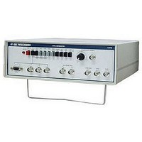
9. IF/RF Switch. Sets modulated output signal (at the IF/RF
10. CH 4/CH 3 Switch. Works in conjunction with rf position of
11. COMPOSITE VIDEO LEVEL Control. Adjusts level and
output jack) to rf or i-f frequency. When this switch is engaged,
the signal at the IF/RF jack is at i-f signal frequency
(45.75MHz) and the CH 4/CH 3 switch has no effect. When
disengaged, the signal at the IF/RF jack is at rf signal frequency
(61.25MHz for CH 3 or 67.25MHz for CH 4).
IFIRF switch. Sets rf output carrier frequency to correspond to
CH 4 or CH 3. When the IF/RF switch is in the rf position
(disengaged) and this switch is disengaged (in the CH 3
position), the output signal at the IF/RF jack corresponds to TV
channel 3 (61.25MHz). When the IF/RF switch is in the RF
position (disengaged) and this switch is engaged (in the CH 4
position), the output signal at the IF/RF jack corresponds to TV
channel 4 (67.25MHz). When the IF/RF switch is in the IF
position (engaged), this switch has no effect on the output.
polarity of composite video signal at COMPOSITE VIDEO
output jack. Counterclockwise rotation produces a composite
video signal with negative going sync pulses (standard signal).
Full counterclockwise rotation of this control provides
maximum output signal with a calibrated level of 1Vp-p into
75Ω. Amplitude reduces to minimum at mid-point. Further
clockwise rotation reverses polarity (positive going sync) and
progressively increases amplitude. Full clockwise rotation of
this control provides an output signal with a level of
approximately 1Vp-p into 75Ω.
approximately 1KHz) is included in the signal at the IF/RF
output jack. When this switch is disengaged, no sound carrier
is included in the signal.
CONTROLS AND INDICATORS (CONT.)
19
12. COMPOSITE VIDEO Jack. Provides a video output for signal
13. IF/RF Jack. Provides approximately 10mV rms (into 75
14. 30Hz Jack. Provides a 30Hz square wave TTL level output
15. COMPosite SYNC Jack. Provides both horizontal and vertical
16. SYNC Vs Jack. Provides vertical sync pulses for external use
17. SYNC Hs Jack. Provides horizontal sync pulses for external
18. B Jack. Provides blue output signal for use with RGB monitors.
substitution directly into the video circuits of a television receiver
and for testing video recorders.
envelope modulated by composite video. Output carrier
frequency can be set to 45.75MHz (IF), 61.25MHz (CH 3) or
67.25MHz (CH 4) by the CH 4/CH 3 and IF/RF switches.
useful for troubleshooting video recorders.
sync pulses for external use such as monitors requiring separate
composite sync or sync trigger for an oscilloscope. Sync pulse
is negative polarity. Output impedance is 75Ω, level is TTL
compatible.
such as vertical sync for RGB monitors or sync trigger for an
oscilloscope. Sync is positive polarity. Output impedance is
75Ω. Level is TTL compatible.
use such as horizontal sync for RGB monitors or sync trigger
for an oscilloscope. Sync pulse is positive polarity. Output
impedance is 75Ω. level is TTL compatible.
Output impedance is 75 Ω and output level is switch selectable
(using the RGB TTL/LOW switch).
Ω) rf