1249B B&K Precision, 1249B Datasheet - Page 36
1249B
Manufacturer Part Number
1249B
Description
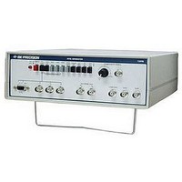
COLOR GENERATORNTSC/RGB
Manufacturer
B&K Precision
Type
NTSC Benchtopr
Specifications of 1249B
Patterns
Bar, Dot, Crosshatch, Raster
Connection Method
RCA, RF, S-Video
Power Source
105,130VAC
Signal Generator Type
NTSC Pattern
Supply Voltage Range
105V To 130V
External Height
86mm
External Width
290mm
External Depth
264mm
Frequency
30 Hz
Equipment Type
NTSC Pattern Generators
Lead Free Status / RoHS Status
na
Lead Free Status / RoHS Status
na
Other names
BK1249B


MAINTENANCE (CONT.)
1.
2.
3.
1.
2.
1. Connect the frequency counter at the junction of R95 and pin
3. Connect the Waveform Monitor and the Vectorscope to the
Color Subcarrier Adjustment
Sound Subcarrier Adjustment
I-F and RF Adjustments
COMPOSITE VIDEO jack (terminated into 75 S2). Set the
Waveform Monitor response to FLAT and the sweep to 2H.
Set the variable amplitude control on the Waveform Monitor
to the CAL position. Set the sync to internal, and turn on the
DC restorer.
6 of IC1 (the right hand side of R95) and adjust C4 for a
reading of 3.579545MHz ±3Hz on the frequency counter.
Press the 4.5MHz switch on the Generator
Connect the frequency counter at the junction of R81 and pin
13 of IC18(the back lead of R81) and adjust L4 for a reading
of 4.49MHz ±10kHz on the frequency counter.
Release the 4.5 MHz switch on the NTSC Generator.
Make sure that the CH 4/CH 3 switch is disengaged (in the
CH 3 position), connect the frequency counter to the IF/RF
jack, and adjust the core of L2 fully clockwise (to the
bottom) or until the frequency counter reads below
61.245MHz.
Now adjust L2 counterclockwise until the frequency
counter reads 61.250MHz ±5KHz. Turn the core an
additional 1/2 turn counter-clockwise. The reading on the
frequency counter should retrain stable.
36
3.
4.
5.
6.
7.
8.
9.
10. Release the CH 4/CH 3 switch. The switch should now be in
1.
Sync Pulse Adjustment
Press the CH 4/CH 3 switch on the NTSC Generator (so that it
is in the CH 4 position).
With the frequency counter still connected to the IF/RF jack,
adjust the core of L3 fully clockwise (to the bottom) or until the
frequency counter reads below 67.245MHz.
Now adjust L3 counterclockwise until the frequency counter
reads 67.250MHz ±5KHz. Turn the core an additional 1/2 turn
counter-clockwise. The reading on the frequency counter
should remain stable.
Press the IF/RF switch on the Generator (so that it is in the IF
position).
Adjust the core of LI fully clockwise (to the bottom) or until
the frequency counter reads below 45.745MHz.
Now adjust L I counterclockwise
reads 45.750MHz ±5 KHz. Turn the core an additional 1/2 turn
counter-clockwise. The reading on the frequency counter
should remain stable.
Release the IF/RF switch (return to channel 4 rf operation).
The counter should now read 67.250MHz ±5KHz. If the
reading is unstable, repeat step 5.
the CH 3 position. The frequency counter should now read
61.250MHz ±5KHz. If the reading is unstable, repeat step 2.
Set the COMPOSITE VIDEO LEVEL control to CAL
position and adjust VR8 for sync pulse amplitude of -40 IRE on
the Waveform Monitor (baseline on zero line).
'
until the frequency counter