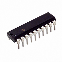
PIC18LF13K22-I/P Microchip Technology, PIC18LF13K22-I/P Datasheet - Page 24

PIC18LF13K22-I/P
Manufacturer Part Number
PIC18LF13K22-I/P
Description
IC PIC MCU FLASH 256KX8 20-PDIP
Manufacturer
Microchip Technology
Series
PIC® XLP™ 18Fr
Datasheets
1.PIC18LF13K22-ISS.pdf
(388 pages)
2.PIC18LF13K22-ISS.pdf
(12 pages)
3.PIC18LF13K22-ISS.pdf
(36 pages)
4.PIC18LF14K22-IP.pdf
(382 pages)
Specifications of PIC18LF13K22-I/P
Program Memory Type
FLASH
Program Memory Size
8KB (4K x 16)
Package / Case
20-DIP (0.300", 7.62mm)
Core Processor
PIC
Core Size
8-Bit
Speed
64MHz
Connectivity
I²C, LIN, SPI, UART/USART
Peripherals
Brown-out Detect/Reset, POR, PWM, WDT
Number Of I /o
17
Eeprom Size
256 x 8
Ram Size
256 x 8
Voltage - Supply (vcc/vdd)
1.8 V ~ 3.6 V
Data Converters
A/D 12x10b
Oscillator Type
Internal
Operating Temperature
-40°C ~ 85°C
Processor Series
PIC18LF
Core
PIC
Data Bus Width
8 bit
Data Ram Size
256 B
Interface Type
I2C, MSSP, SPI, USART
Maximum Clock Frequency
32 KHz
Number Of Programmable I/os
18
Number Of Timers
4
Operating Supply Voltage
1.8 V to 3.6 V
Maximum Operating Temperature
+ 125 C
Mounting Style
Through Hole
3rd Party Development Tools
52715-96, 52716-328, 52717-734, 52712-325, EWPIC18
Development Tools By Supplier
PG164130, DV164035, DV244005, DV164005
Minimum Operating Temperature
- 40 C
On-chip Adc
10 bit, 12 Channel
Lead Free Status / RoHS Status
Lead free / RoHS Compliant
Lead Free Status / RoHS Status
Lead free / RoHS Compliant, Lead free / RoHS Compliant
- PIC18LF13K22-ISS PDF datasheet
- PIC18LF13K22-ISS PDF datasheet #2
- PIC18LF13K22-ISS PDF datasheet #3
- PIC18LF14K22-IP PDF datasheet #4
- Current page: 24 of 388
- Download datasheet (4Mb)
PIC18F1XK22/LF1XK22
TABLE 2-2:
2.10
A Phase Locked Loop (PLL) circuit is provided as an
option for users who wish to use a lower-frequency
external oscillator or to operate at 32 MHz or 64 MHz
with the HFINTOSC. The PLL is designed for an input
frequency from 4 MHz to 16 MHz. The PLL multiplies
its input frequency by a factor of four when the PLL is
enabled. This may be useful for customers who are
concerned with EMI, due to high-frequency crystals.
Two bits control the PLL: the PLL_EN bit of the
CONFIG1H Configuration register and the PLLEN bit of
the OSCTUNE register. The PLL is enabled when the
PLL_EN bit is set and it is under software control when
the PLL_EN bit is cleared. Refer to Table 2-3 and
Table 2-4 for more information.
TABLE 2-3:
TABLE 2-4:
DS41365D-page 24
Sleep/POR
Sleep/POR
Sleep/POR
HF INTOSC
LF INTOSC
EXTRC
Mode
PLL_EN
HS
EC
LP
XT
1
0
0
4x Phase Lock Loop Frequency
Multiplier
Switch From
Enable (PLL_EN)
PLL CONFIG1H
EXAMPLES OF DELAYS DUE TO CLOCK SWITCHING
PLL CONFIGURATION
PLL CONFIG1H/SOFTWARE
ENABLE CLOCK SOURCE
RESTRICTIONS
8/16 MHz
Yes
Yes
Yes
Yes
Yes
No
PLLEN
x
1
0
Enable (PLLEN)
PLL Software
PLL disabled
PLL enabled
PLL enabled
8/16 MHz
PLL Status
No
No
No
No
No
No
Preliminary
HFINTOSC
LFINTOSC
LP, XT, HS
Switch To
EC, RC
2.11
Two-Speed Start-up mode provides additional power
savings by minimizing the latency between external
Oscillator Start-up Timer (OST) and code execution. In
applications that make heavy use of the Sleep mode,
Two-Speed Start-up will remove the OST period, which
can reduce the overall power consumption of the
device.
Two-Speed Start-up mode is enabled by setting the
IESO bit of the CONFIG1H Configuration register. With
Two-Speed Start-up enabled, the device will execute
instructions using the internal oscillator during the
Primary External Oscillator OST period.
When the system clock is set to the Primary External
Oscillator and the oscillator is configured for LP, XT or
HS modes, the device will not execute code during the
OST period. The OST will suspend program execution
until 1024 oscillations are counted. Two-Speed Start-
up mode minimizes the delay in code execution by
operating from the internal oscillator while the OST is
active. The system clock will switch back to the Primary
External Oscillator after the OST period has expired.
Two-speed Start-up will become active after:
• Power-on Reset (POR)
• Power-up Timer (PWRT), if enabled
• Wake-up from Sleep
The OSTS bit of the OSCCON register reports which
oscillator the device is currently using for operation.
The device is running from the oscillator defined by the
FOSC bits of the CONFIG1H Configuration register
when the OSTS bit is set. The device is running from
the internal oscillator when the OSTS bit is clear.
Two-Speed Start-up Mode
Oscillator Warm-up Delay (T
2010 Microchip Technology Inc.
1024 clock cycles
Oscillator Delay
8 Clock Cycles
WARM
)
Related parts for PIC18LF13K22-I/P
Image
Part Number
Description
Manufacturer
Datasheet
Request
R

Part Number:
Description:
Manufacturer:
Microchip Technology Inc.
Datasheet:

Part Number:
Description:
Manufacturer:
Microchip Technology Inc.
Datasheet:

Part Number:
Description:
Manufacturer:
Microchip Technology Inc.
Datasheet:

Part Number:
Description:
Manufacturer:
Microchip Technology Inc.
Datasheet:

Part Number:
Description:
Manufacturer:
Microchip Technology Inc.
Datasheet:

Part Number:
Description:
Manufacturer:
Microchip Technology Inc.
Datasheet:

Part Number:
Description:
Manufacturer:
Microchip Technology Inc.
Datasheet:

Part Number:
Description:
Manufacturer:
Microchip Technology Inc.
Datasheet:


