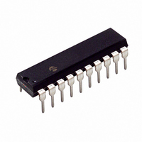
PIC18LF13K22-I/P Microchip Technology, PIC18LF13K22-I/P Datasheet - Page 346

PIC18LF13K22-I/P
Manufacturer Part Number
PIC18LF13K22-I/P
Description
IC PIC MCU FLASH 256KX8 20-PDIP
Manufacturer
Microchip Technology
Series
PIC® XLP™ 18Fr
Datasheets
1.PIC18LF13K22-ISS.pdf
(388 pages)
2.PIC18LF13K22-ISS.pdf
(12 pages)
3.PIC18LF13K22-ISS.pdf
(36 pages)
4.PIC18LF14K22-IP.pdf
(382 pages)
Specifications of PIC18LF13K22-I/P
Program Memory Type
FLASH
Program Memory Size
8KB (4K x 16)
Package / Case
20-DIP (0.300", 7.62mm)
Core Processor
PIC
Core Size
8-Bit
Speed
64MHz
Connectivity
I²C, LIN, SPI, UART/USART
Peripherals
Brown-out Detect/Reset, POR, PWM, WDT
Number Of I /o
17
Eeprom Size
256 x 8
Ram Size
256 x 8
Voltage - Supply (vcc/vdd)
1.8 V ~ 3.6 V
Data Converters
A/D 12x10b
Oscillator Type
Internal
Operating Temperature
-40°C ~ 85°C
Processor Series
PIC18LF
Core
PIC
Data Bus Width
8 bit
Data Ram Size
256 B
Interface Type
I2C, MSSP, SPI, USART
Maximum Clock Frequency
32 KHz
Number Of Programmable I/os
18
Number Of Timers
4
Operating Supply Voltage
1.8 V to 3.6 V
Maximum Operating Temperature
+ 125 C
Mounting Style
Through Hole
3rd Party Development Tools
52715-96, 52716-328, 52717-734, 52712-325, EWPIC18
Development Tools By Supplier
PG164130, DV164035, DV244005, DV164005
Minimum Operating Temperature
- 40 C
On-chip Adc
10 bit, 12 Channel
Lead Free Status / RoHS Status
Lead free / RoHS Compliant
Lead Free Status / RoHS Status
Lead free / RoHS Compliant, Lead free / RoHS Compliant
- PIC18LF13K22-ISS PDF datasheet
- PIC18LF13K22-ISS PDF datasheet #2
- PIC18LF13K22-ISS PDF datasheet #3
- PIC18LF14K22-IP PDF datasheet #4
- Current page: 346 of 388
- Download datasheet (4Mb)
PIC18F1XK22/LF1XK22
25.10 Memory Programming Requirements
DS41365D-page 346
DC CHARACTERISTICS
D110
D113
D120
D121
D122
D123
D124
D130
D131
D132
D133
D134
Note 1:
Param
No.
2:
3:
4:
†
V
I
E
V
T
T
T
E
V
I
I
T
T
DDP
PPPGM
DDPGM
Sym.
DEW
RETD
REF
PEW
RETD
PP
D
DRW
P
PEW
Data in “Typ” column is at 3.0V, 25°C unless otherwise stated. These parameters are for design guidance only and are
not tested.
These specifications are for programming the on-chip program memory through the use of table write instructions.
Refer to Section 5.8 “Using the Data EEPROM” for a more detailed discussion on data EEPROM endurance.
Required only if single-supply programming is disabled.
The MPLAB ICD 2 does not support variable V
between the ICD 2 and target system when programming or debugging with the ICD 2.
Internal Program Memory
Programming Specifications
Voltage on MCLR/V
Supply Current during Programming
Data EEPROM Memory
Byte Endurance
V
Erase/Write Cycle Time
Characteristic Retention
Number of Total Erase/Write Cycles
before Refresh
Program Flash Memory
Cell Endurance
V
Voltage on MCLR/V
Erase/Program
V
V
Current on MCLR/V
Erase/Write
Current on V
Erase/Write cycle time
Characteristic Retention
DD
DD
DD
DD
for Read/Write
for Read
for Bulk Erase
for Write or Row Erase
Characteristic
DD
(2)
during Erase/Write
PP
PP
PP
/RA3 pin
during
during
(2)
(1)
Preliminary
Standard Operating Conditions (unless otherwise stated)
Operating temperature
V
PP
DD
100K
V
V
Min.
TBD
10k
1.8
1M
8.0
output. Circuitry to limit the ICD 2 V
—
40
40
—
—
—
—
MIN
MIN
+ 4.5
Typ†
10M
2.7
—
—
—
—
—
—
—
—
—
—
—
4
Max.
-40°C T
3.6
9.0
5.0
5.0
2.8
10
—
—
—
—
—
—
—
—
—
9
Units
A
Year
Year
E/W
E/W
E/W
mA
mA
mA
ms
ms
+125°C
V
V
V
V
V
V
2010 Microchip Technology Inc.
PP
voltage must be placed
(Note 3, Note 4)
-40C to +85C
Using EECON to read/write
Provided no other
specifications are violated
-40°C to +85°C
Temperature during program-
ming: 10°C T
Temperature during program-
ming: 10°C T
Temperature during program-
ming: 10°C T
V
voltage
V
voltage
Temperature during program-
ming: 10°C T
Temperature during program-
ming: 10°C T
Temperature during program-
ming: 10°C T
Provided no other
specifications are violated
MIN
MAX
= Minimum operating
= Maximum operating
Conditions
A
A
A
A
A
A
40°C
40°C
40°C
40°C
40°C
40°C
Related parts for PIC18LF13K22-I/P
Image
Part Number
Description
Manufacturer
Datasheet
Request
R

Part Number:
Description:
Manufacturer:
Microchip Technology Inc.
Datasheet:

Part Number:
Description:
Manufacturer:
Microchip Technology Inc.
Datasheet:

Part Number:
Description:
Manufacturer:
Microchip Technology Inc.
Datasheet:

Part Number:
Description:
Manufacturer:
Microchip Technology Inc.
Datasheet:

Part Number:
Description:
Manufacturer:
Microchip Technology Inc.
Datasheet:

Part Number:
Description:
Manufacturer:
Microchip Technology Inc.
Datasheet:

Part Number:
Description:
Manufacturer:
Microchip Technology Inc.
Datasheet:

Part Number:
Description:
Manufacturer:
Microchip Technology Inc.
Datasheet:


