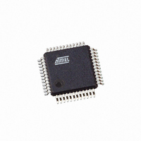
AT91SAM7S32B-AU Atmel, AT91SAM7S32B-AU Datasheet - Page 763

AT91SAM7S32B-AU
Manufacturer Part Number
AT91SAM7S32B-AU
Description
IC MCU ARM7 32KB FLASH 48LQFP
Manufacturer
Atmel
Series
AT91SAMr
Datasheet
1.AT91SAM7S16-MU.pdf
(779 pages)
Specifications of AT91SAM7S32B-AU
Core Processor
ARM7
Core Size
16/32-Bit
Speed
55MHz
Connectivity
I²C, SPI, SSC, UART/USART
Peripherals
Brown-out Detect/Reset, DMA, POR, PWM, WDT
Number Of I /o
21
Program Memory Size
32KB (32K x 8)
Program Memory Type
FLASH
Ram Size
8K x 8
Voltage - Supply (vcc/vdd)
1.65 V ~ 1.95 V
Data Converters
A/D 8x10b
Oscillator Type
Internal
Operating Temperature
-40°C ~ 85°C
Package / Case
48-LQFP
Cpu Family
91S
Device Core
ARM7TDMI
Device Core Size
32b
Frequency (max)
55MHz
Interface Type
SPI/TWI/USART
Total Internal Ram Size
8KB
# I/os (max)
21
Number Of Timers - General Purpose
3
Operating Supply Voltage (typ)
1.8/3.3V
Operating Supply Voltage (max)
1.95/3.6V
Operating Supply Voltage (min)
1.65/3V
On-chip Adc
8-chx10-bit
Instruction Set Architecture
RISC
Operating Temp Range
-40C to 85C
Operating Temperature Classification
Industrial
Mounting
Surface Mount
Pin Count
48
Package Type
LQFP
Package
48LQFP
Family Name
AT91
Maximum Speed
55 MHz
Operating Supply Voltage
1.8|3.3 V
Data Bus Width
32 Bit
Number Of Programmable I/os
21
Number Of Timers
3
For Use With
AT91SAM-ICE - EMULATOR FOR AT91 ARM7/ARM9AT91SAM7S-EK - KIT EVAL FOR ARM AT91SAM7S
Lead Free Status / RoHS Status
Lead free / RoHS Compliant
Eeprom Size
-
Lead Free Status / Rohs Status
Compliant
Available stocks
Company
Part Number
Manufacturer
Quantity
Price
Part Number:
AT91SAM7S32B-AU
Manufacturer:
MICROCHIP/微芯
Quantity:
20 000
- Current page: 763 of 779
- Download datasheet (11Mb)
6175K–ATARM–30-Aug-10
Version
6175F
Comments
“Features” on page 1
Manchester Encoder/Decoder removed from USART.
“Features” on page
Pinout”Section 39. ”AT91SAM7S Ordering
family.
Section 4.1 ”64-lead LQFP and 64-pad QFN Package Outlines”
pad QFN Package
Figure 8-1 on page 20
Section 20. ”Embedded Flash Controller (EFC)” EFC0 and EFC1 on AT91SAM7S512 explained.
Section 10.1 ”User
Table 10-1
ADC Block diagram Figure 35-1 on page 479 - dedicated and I/O analog inputs differentiated
”ADC Timings” page 485 WARNING ”...See the section ADC Characteristics....” typo fixed.
Section 21. ”Fast Flash Programming Interface (FFPI)”, AT91SAM7S512 instructions added to Section
21.2.5.6, and Section 21.2.5.7 on page 155, Section 21.3.4.6 and Section 21.3.4.7 on page 162.
Table 21-1 on page 147 PMD and PGMNVALID bus size for AT91SAM7S32 is [7:0].
AIC, Section 24.7.3.1 ”Priority Controller” SRCTYPTE field is in AIC_SMR register, not AIC_SVR
“Advanced Interrupt Controller (AIC) User Interface” , Table 24-2 on page 198 note 2 ref to PID bit fields
AT91SAM7 Boot Program Section 22.5 ”SAM-BA Boot” SAM-BA boot principle changed Section 22.2
”Flow Diagram”replaced Figure 22-1 and Figure 22-2 on page 165
DBGU: ”ARCH: Architecture Identifier” page 259: updated
Functional Block Diagram in Figure 27-1 on page 238 and Section 27.5.12 ”Debug Unit Force NTRST
Register”ice_nreset signal replaced with pad name, Power-on Reset (power_on_reset.)
“Peripheral DMA Controller (PDC)” User interface description updated page 173. Correct typo to
“
PIO, Section 15.4.4 ”Output Control” typo corrected
Section 15.4.1 ”Pull-up Resistor Control”, ref to resistor value removed.
Figure 15-3 ”I/O Line Control Logic” page 82, 0 and 1 inverted in the MUX controlled by PIO_MDSR.
”PMC Master Clock Register” on page 231 Corrected name of bitfield “PRES”
Note defining PIDx added to “PMC Peripheral Clock Enable Register” , ”PMC Peripheral Clock Disable
Register” page 226 and
Table 26-2 on page 222: footnotes reassigned.
PWM, updated waveform generation Section 33.5.3.3 ”Changing the Duty Cycle or the Period” page 430.
RSTC; added info on startup counter on crystal oscillator Section 13.3.1 ”Reset Controller Overview”
RTT, added note to ”Functional Description” page 73
ENDTX”
bit field name in Section 23.3.3 ”Transfer Counters”
and
Table 10-2
Outlines”added (replace Mechanical Overview).
Interface”User Peripherals are mapped between 0xF000 0000 and 0xFFFF EFFF.
1,
(global) QFN packages changed to 64- and 48-pad QFN
Table 1-1, “Configuration Summary,” on page
Peripheral and System Controller Memory Mapping has been condensed.
SYSIRQ changed to SYSC in “Peripheral Identifiers”
Information”and global, AT91SAM7S512 added to product
AT91SAM7S Series Preliminary
and
Section 4.3 ”48-lead LQFP and 48-
3,
Section 4. ”Package and
Change
Request
Ref.
#2748
rfo review
#3052
#2830
#2284
#2748
#2512
#2548
#3050
#2832
05-460
05-346
05-497
#3053
#1603
#2468
#2748
#1677
#3005
#2522
753
Related parts for AT91SAM7S32B-AU
Image
Part Number
Description
Manufacturer
Datasheet
Request
R

Part Number:
Description:
KIT EVAL FOR ARM AT91SAM7S
Manufacturer:
Atmel
Datasheet:

Part Number:
Description:
MCU, MPU & DSP Development Tools KICKSTART KIT ATMEL AT91SAM7S
Manufacturer:
IAR Systems

Part Number:
Description:
DEV KIT FOR AVR/AVR32
Manufacturer:
Atmel
Datasheet:

Part Number:
Description:
INTERVAL AND WIPE/WASH WIPER CONTROL IC WITH DELAY
Manufacturer:
ATMEL Corporation
Datasheet:

Part Number:
Description:
Low-Voltage Voice-Switched IC for Hands-Free Operation
Manufacturer:
ATMEL Corporation
Datasheet:

Part Number:
Description:
MONOLITHIC INTEGRATED FEATUREPHONE CIRCUIT
Manufacturer:
ATMEL Corporation
Datasheet:

Part Number:
Description:
AM-FM Receiver IC U4255BM-M
Manufacturer:
ATMEL Corporation
Datasheet:

Part Number:
Description:
Monolithic Integrated Feature Phone Circuit
Manufacturer:
ATMEL Corporation
Datasheet:

Part Number:
Description:
Multistandard Video-IF and Quasi Parallel Sound Processing
Manufacturer:
ATMEL Corporation
Datasheet:

Part Number:
Description:
High-performance EE PLD
Manufacturer:
ATMEL Corporation
Datasheet:

Part Number:
Description:
8-bit Flash Microcontroller
Manufacturer:
ATMEL Corporation
Datasheet:

Part Number:
Description:
2-Wire Serial EEPROM
Manufacturer:
ATMEL Corporation
Datasheet:


