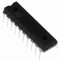
ST7FLITE25F2B6 STMicroelectronics, ST7FLITE25F2B6 Datasheet - Page 66

ST7FLITE25F2B6
Manufacturer Part Number
ST7FLITE25F2B6
Description
IC MCU 8BIT 8K FLASH 20DIP
Manufacturer
STMicroelectronics
Series
ST7r
Datasheet
1.ST7FLITE20F2B6.pdf
(133 pages)
Specifications of ST7FLITE25F2B6
Core Processor
ST7
Core Size
8-Bit
Speed
8MHz
Connectivity
SPI
Peripherals
LVD, POR, PWM, WDT
Number Of I /o
15
Program Memory Size
8KB (8K x 8)
Program Memory Type
FLASH
Ram Size
384 x 8
Voltage - Supply (vcc/vdd)
2.4 V ~ 5.5 V
Data Converters
A/D 7x10b
Oscillator Type
Internal
Operating Temperature
-40°C ~ 85°C
Package / Case
20-DIP (0.300", 7.62mm)
Processor Series
ST7FLITE2x
Core
ST7
Data Bus Width
8 bit
Data Ram Size
384 B
Interface Type
SPI
Maximum Clock Frequency
8 MHz
Number Of Programmable I/os
15
Number Of Timers
4 bit
Operating Supply Voltage
2.4 V to 5.5 V
Maximum Operating Temperature
+ 85 C
Mounting Style
Through Hole
Development Tools By Supplier
ST7FLIT2-COS/COM, ST7FLITE-SK/RAIS, ST7MDT10-DVP3, ST7MDT10-EMU3, STX-RLINK
Minimum Operating Temperature
- 40 C
On-chip Adc
13 bit
For Use With
497-5858 - EVAL BOARD PLAYBACK ST7FLITE497-5049 - KIT STARTER RAISONANCE ST7FLITE
Lead Free Status / RoHS Status
Lead free / RoHS Compliant
Eeprom Size
-
Lead Free Status / Rohs Status
In Transition
Other names
497-4858
Available stocks
Company
Part Number
Manufacturer
Quantity
Price
ST7LITE2
LITE TIMER (Cont’d)
11.3.3 Functional Description
11.3.3.1 Timebase Counter 1
The 8-bit value of Counter 1 cannot be read or
written by software. After an MCU reset, it starts
incrementing from 0 at a frequency of f
overflow event occurs when the counter rolls over
from F9h to 00h. If f
riod between two counter overflow events is 1 ms.
This period can be doubled by setting the TB bit in
the LTCSR1 register.
When Counter 1 overflows, the TB1F bit is set by
hardware and an interrupt request is generated if
the TB1IE bit is set. The TB1F bit is cleared by
software reading the LTCSR1 register.
11.3.3.2 Input Capture
The 8-bit input capture register is used to latch the
free-running upcounter (Counter 1) 1 after a rising
or falling edge is detected on the LTIC pin. When
an input capture occurs, the ICF bit is set and the
LTICR1 register contains the MSB of Counter 1.
Figure 41. Input Capture Timing Diagram.
66/133
1
LTICR REGISTER
8-bit COUNTER 1
ICF FLAG
LTIC PIN
f
OSC
f
CPU
/32
OSC
01h
= 8 MHz, then the time pe-
(@ 8MHz f
4µs
02h
xxh
OSC
)
OSC
03h
/32. An
04h
An interrupt is generated if the ICIE bit is set. The
ICF bit is cleared by reading the LTICR register.
The LTICR is a read-only register and always con-
tains the data from the last input capture. Input
capture is inhibited if the ICF bit is set.
11.3.3.3 Timebase Counter 2
Counter 2 is an 8-bit autoreload upcounter. It can
be read by accessing the LTCNTR register. After
an MCU reset, it increments at a frequency of
f
LTARR register. A counter overflow event occurs
when the counter rolls over from FFh to the
LTARR reload value. Software can write a new
value at anytime in the LTARR register, this value
will be automatically loaded in the counter when
the next overflow occurs.
When Counter 2 overflows, the TB2F bit in the
LTCSR2 register is set by hardware and an inter-
rupt request is generated if the TB2IE bit is set.
The TB2F bit is cleared by software reading the
LTCSR2 register.
OSC
05h
/32 starting from the value stored in the
04h
06h
07h
LTIC REGISTER
07h
CLEARED
READING
BY S/W
t


