ST72F324BJ6B6 STMicroelectronics, ST72F324BJ6B6 Datasheet - Page 114
ST72F324BJ6B6
Manufacturer Part Number
ST72F324BJ6B6
Description
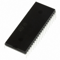
MCU 8BIT 32KB FLASH/ROM 42-SDIP
Manufacturer
STMicroelectronics
Series
ST7r
Datasheet
1.ST72F324BJ6B6.pdf
(193 pages)
Specifications of ST72F324BJ6B6
Core Processor
ST7
Core Size
8-Bit
Speed
8MHz
Connectivity
SCI, SPI
Peripherals
LVD, POR, PWM, WDT
Number Of I /o
32
Program Memory Size
32KB (32K x 8)
Program Memory Type
FLASH
Ram Size
1K x 8
Voltage - Supply (vcc/vdd)
3.8 V ~ 5.5 V
Data Converters
A/D 12x10b
Oscillator Type
Internal
Operating Temperature
-40°C ~ 85°C
Package / Case
42-SDIP (0.600", 15.24mm)
Controller Family/series
ST7
No. Of I/o's
32
Ram Memory Size
1KB
Cpu Speed
8MHz
No. Of Timers
2
Embedded Interface Type
SCI, SPI
No. Of Pwm Channels
3
Processor Series
ST72F3x
Core
ST7
Data Bus Width
8 bit
Data Ram Size
1 KB
Interface Type
SCI, SPI
Maximum Clock Frequency
8 MHz
Number Of Programmable I/os
32
Number Of Timers
3
Maximum Operating Temperature
+ 85 C
Mounting Style
Through Hole
Development Tools By Supplier
ST7232X-EVAL, ST7MDT20-DVP3, ST7MDT20J-EMU3, STX-RLINK
Minimum Operating Temperature
- 40 C
On-chip Adc
10 bit, 12 Channel
For Use With
497-6421 - BOARD EVAL DGTL BATT CHGR DESIGN497-5046 - KIT TOOL FOR ST7/UPSD/STR7 MCU
Lead Free Status / RoHS Status
Lead free / RoHS Compliant
Eeprom Size
-
Lead Free Status / Rohs Status
Details
Other names
497-5589-5


On-chip peripherals
Note:
114/193
Overrun error
An overrun error occurs when a character is received when RDRF has not been reset. Data
can not be transferred from the shift register to the RDR register as long as the RDRF bit is
not cleared.
When a overrun error occurs:
●
●
●
●
The OR bit is reset by an access to the SCISR register followed by a SCIDR register read
operation.
Noise error
Oversampling techniques are used for data recovery by discriminating between valid
incoming data and noise. Normal data bits are considered valid if three consecutive samples
(8th, 9th, 10th) have the same bit value, otherwise the NF flag is set. In the case of start bit
detection, the NF flag is set on the basis of an algorithm combining both valid edge
detection and three samples (8th, 9th, 10th). Therefore, to prevent the NF flag from being
set during start bit reception, there should be a valid edge detection as well as three valid
samples.
When noise is detected in a frame:
●
●
●
The NF flag is reset by a SCISR register read operation followed by a SCIDR register read
operation.
During reception, if a false start bit is detected (for example, 8th, 9th, 10th samples are
011,101,110), the frame is discarded and the receiving sequence is not started for this
frame. There is no RDRF bit set for this frame and the NF flag is set internally (not
accessible to the user). This NF flag is accessible along with the RDRF bit when a next valid
frame is received.
If the application Start bit is not long enough to match the above requirements, then the NF
Flag may get set due to the short Start bit. In this case, the NF flag may be ignored by the
application software when the first valid byte is received.
See also
The OR bit is set.
The RDR content will not be lost.
The shift register will be overwritten.
An interrupt is generated if the RIE bit is set and the I bit is cleared in the CCR register.
The NF flag is set at the rising edge of the RDRF bit.
Data is transferred from the Shift register to the SCIDR register.
No interrupt is generated. However this bit rises at the same time as the RDRF bit
which itself generates an interrupt.
Noise error causes on page
119.
ST72324Bxx
Related parts for ST72F324BJ6B6
Image
Part Number
Description
Manufacturer
Datasheet
Request
R

Part Number:
Description:
STMicroelectronics [RIPPLE-CARRY BINARY COUNTER/DIVIDERS]
Manufacturer:
STMicroelectronics
Datasheet:
Part Number:
Description:
STMicroelectronics [LIQUID-CRYSTAL DISPLAY DRIVERS]
Manufacturer:
STMicroelectronics
Datasheet:

Part Number:
Description:
BOARD EVAL FOR MEMS SENSORS
Manufacturer:
STMicroelectronics
Datasheet:
Part Number:
Description:
NPN TRANSISTOR POWER MODULE
Manufacturer:
STMicroelectronics
Datasheet:
Part Number:
Description:
TURBOSWITCH ULTRA-FAST HIGH VOLTAGE DIODE
Manufacturer:
STMicroelectronics
Datasheet:
Part Number:
Description:
Manufacturer:
STMicroelectronics
Datasheet:
Part Number:
Description:
DIODE / SCR MODULE
Manufacturer:
STMicroelectronics
Datasheet:
Part Number:
Description:
DIODE / SCR MODULE
Manufacturer:
STMicroelectronics
Datasheet:
Part Number:
Description:
Search -----> STE16N100
Manufacturer:
STMicroelectronics
Datasheet:
Part Number:
Description:
Search ---> STE53NA50
Manufacturer:
STMicroelectronics
Datasheet:
Part Number:
Description:
NPN Transistor Power Module
Manufacturer:
STMicroelectronics
Datasheet: