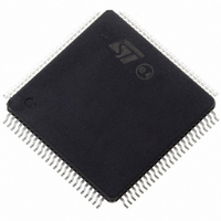
ST10R172LT6 STMicroelectronics, ST10R172LT6 Datasheet - Page 32

ST10R172LT6
Manufacturer Part Number
ST10R172LT6
Description
IC MCU 16BIT LV ROMLESS 100-TQFP
Manufacturer
STMicroelectronics
Series
ST10r
Datasheet
1.ST10R172LT6.pdf
(68 pages)
Specifications of ST10R172LT6
Core Processor
ST10
Core Size
16-Bit
Speed
50MHz
Connectivity
EBI/EMI, SSP, UART/USART
Peripherals
POR, PWM, WDT
Number Of I /o
77
Program Memory Type
ROMless
Ram Size
1K x 8
Voltage - Supply (vcc/vdd)
3 V ~ 3.6 V
Oscillator Type
Internal
Operating Temperature
-40°C ~ 85°C
Package / Case
144-TQFP, 144-VQFP
Processor Series
ST10R1x
Core
ST10
Data Bus Width
16 bit
Data Ram Size
1 KB
Interface Type
SSP, USART
Maximum Clock Frequency
50 MHz
Number Of Programmable I/os
77
Number Of Timers
5
Maximum Operating Temperature
+ 85 C
Mounting Style
SMD/SMT
Minimum Operating Temperature
- 40 C
On-chip Adc
8 bit
Lead Free Status / RoHS Status
Contains lead / RoHS non-compliant
Eeprom Size
-
Program Memory Size
-
Data Converters
-
Lead Free Status / Rohs Status
In Transition
Other names
497-2044
Available stocks
Company
Part Number
Manufacturer
Quantity
Price
Company:
Part Number:
ST10R172LT6
Manufacturer:
MPS
Quantity:
1 000
Company:
Part Number:
ST10R172LT6
Manufacturer:
STMicroelectronics
Quantity:
10 000
Company:
Part Number:
ST10R172LT6VJ029CNX
Manufacturer:
CYPRESS
Quantity:
10
ST10R172L - ELECTRICAL CHARACTERISTICS
Remarks on 5 volt tolerant (5T) and 5 volt fail-safe (5S) pins
The 5V tolerant input and output pins can sustain an absolute maximum external voltage of
5.5V.
However, signals on unterminated bus lines might have overshoot above 5.5V, presenting
latchup and hot carrier risks. While these risks are under evaluation, observe the following se-
curity recommendations:
•
•
Power supply failure condition
The power supply failure condition is a state where the chip is NOT supplied but is connected
to active signal lines. There are several cases:
•
•
•
•
•
•
•
32/68
1
Maximum peak voltage on 5V tolerant pin with respect to ground ( V
If the ringing of the external signal exceeds 6V, then clip the signal to the 5V supply.
3.3V external lines on 3.3V (3T) pin on the non powered chip: ...............NOT Acceptable
3.3V external lines on 5V tolerant (5T) pin on the non powered chip: ............. Acceptable
The 5V tolerant buffer do not leak: external signals not altered. No reliability problem.
3.3V external lines on 5V fail-safe (5S) pin on the non powered chip: ............ Acceptable
The 5V tolerant buffer do not leak: external signals not altered. No reliability problem.
5.5V external lines on 5V tolerant (5T) pin on the non powered chip: ............. Acceptable
For VERY SHORT times only: the buffers do not leak (external signals not altered) but
there is a fast degradation of the gate oxides in the buffers. The total maximum time under
this stress condition is 2 days. This limits this configuration to short power-up/down
sequences. For 10 year life time, the maximum duty factor is 1/1800 allowing e.g. a
maximum stress duration of 48 seconds per day.
5.5V external lines on 5V fail-safe (5S) pin on the non powered chip: ............ Acceptable
6V transient signals on 5V tolerant (5T) pin on the non powered chip: ...NOT Acceptable
6V transient signals on 5V fail-safe (5S) pin on the non powered chip:.......... Acceptable
SS
)= +6 V


