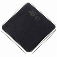
ST10R172LT6 STMicroelectronics, ST10R172LT6 Datasheet - Page 39

ST10R172LT6
Manufacturer Part Number
ST10R172LT6
Description
IC MCU 16BIT LV ROMLESS 100-TQFP
Manufacturer
STMicroelectronics
Series
ST10r
Datasheet
1.ST10R172LT6.pdf
(68 pages)
Specifications of ST10R172LT6
Core Processor
ST10
Core Size
16-Bit
Speed
50MHz
Connectivity
EBI/EMI, SSP, UART/USART
Peripherals
POR, PWM, WDT
Number Of I /o
77
Program Memory Type
ROMless
Ram Size
1K x 8
Voltage - Supply (vcc/vdd)
3 V ~ 3.6 V
Oscillator Type
Internal
Operating Temperature
-40°C ~ 85°C
Package / Case
144-TQFP, 144-VQFP
Processor Series
ST10R1x
Core
ST10
Data Bus Width
16 bit
Data Ram Size
1 KB
Interface Type
SSP, USART
Maximum Clock Frequency
50 MHz
Number Of Programmable I/os
77
Number Of Timers
5
Maximum Operating Temperature
+ 85 C
Mounting Style
SMD/SMT
Minimum Operating Temperature
- 40 C
On-chip Adc
8 bit
Lead Free Status / RoHS Status
Contains lead / RoHS non-compliant
Eeprom Size
-
Program Memory Size
-
Data Converters
-
Lead Free Status / Rohs Status
In Transition
Other names
497-2044
Available stocks
Company
Part Number
Manufacturer
Quantity
Price
Company:
Part Number:
ST10R172LT6
Manufacturer:
MPS
Quantity:
1 000
Company:
Part Number:
ST10R172LT6
Manufacturer:
STMicroelectronics
Quantity:
10 000
Company:
Part Number:
ST10R172LT6VJ029CNX
Manufacturer:
CYPRESS
Quantity:
10
Prescaler operation
Set when pins P0.15-13 (P0H.7-5) equal ’001’ during reset, the CPU clock is derived from the
internal oscillator (input clock signal) by a 2:1 prescaler.
The frequency of f
duration of an individual TCL) is defined by the period of the input clock f
The timings listed in the AC characteristics that refer to TCLs therefore can be calculated
using the period of f
Note that if the bit OWDDIS in SYSCON register is cleared, the PLL runs on its free-running
frequency and delivers the clock signal for the Oscillator Watchdog. If bit OWDDIS is set, then
the PLL is switched off.
Direct drive
When pins P0.15-13 (P0H.7-5) equal ’011’ during reset, the on-chip phase locked loop is
disabled and the CPU clock is driven from the internal oscillator with the input clock signal.
The frequency of f
(i.e. the duration of an individual TCL) is defined by the duty cycle of the input clock f
The TCL timing below must be calculated using the minimum possible TCL which can be
calculated by the formula:
For two consecutive TCLs the deviation caused by the duty cycle of f
the duration of 2TCL is always 1/f
only once for timings that require an odd number of TCLs (1,3,...). Timings that require an
even number of TCLs (2,4,...) may use the formula:
0
P0.15-13 (P0H.7-5)
1
0
0
0
1) The maximum depends on the duty cycle of the external clock signal. The maxi-
mum input frequency is 25 MHz when using an external crystal oscillator, but
higher frequencies can be applied with an external clock source.
0
0
1
1
0
0
CPU
0
1
0
1
CPU
XTAL
Table 12 CPU clock generation mechanisms
is half the frequency of f
directly follows the frequency of f
for any TCL.
CPU frequency
f
F
F
F
F
TCL
F
CPU
XTAL
XTAL
XTAL
XTAL
XTAL
min
= f
* 5
* 1
* 1.5
/ 2
* 2.5
XTAL
XTAL
=
1 f
. Therefore, the minimum value TCL
* F
XTAL
ST10R172L - ELECTRICAL CHARACTERISTICS
External clock
input range 10-
50MHz
2 to 10 MHz
1 to 50 MHz
6.66 to 33.33 MHz
2 to 100 MHz
4 to 20 MHz
XTAL
DC
min
and the high and low time of f
2TCL
DC
XTAL
=
=
so the high and low time of f
duty cycle
1 f
XTAL
Notes
Direct drive
CPU clock via 2:1 prescaler
XTAL
.
XTAL
is compensated so
min
1)
.
has to be used
CPU
XTAL
(i.e. the
CPU
39/68
.
1


