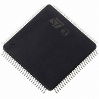
ST10R172LT6 STMicroelectronics, ST10R172LT6 Datasheet - Page 52

ST10R172LT6
Manufacturer Part Number
ST10R172LT6
Description
IC MCU 16BIT LV ROMLESS 100-TQFP
Manufacturer
STMicroelectronics
Series
ST10r
Datasheet
1.ST10R172LT6.pdf
(68 pages)
Specifications of ST10R172LT6
Core Processor
ST10
Core Size
16-Bit
Speed
50MHz
Connectivity
EBI/EMI, SSP, UART/USART
Peripherals
POR, PWM, WDT
Number Of I /o
77
Program Memory Type
ROMless
Ram Size
1K x 8
Voltage - Supply (vcc/vdd)
3 V ~ 3.6 V
Oscillator Type
Internal
Operating Temperature
-40°C ~ 85°C
Package / Case
144-TQFP, 144-VQFP
Processor Series
ST10R1x
Core
ST10
Data Bus Width
16 bit
Data Ram Size
1 KB
Interface Type
SSP, USART
Maximum Clock Frequency
50 MHz
Number Of Programmable I/os
77
Number Of Timers
5
Maximum Operating Temperature
+ 85 C
Mounting Style
SMD/SMT
Minimum Operating Temperature
- 40 C
On-chip Adc
8 bit
Lead Free Status / RoHS Status
Contains lead / RoHS non-compliant
Eeprom Size
-
Program Memory Size
-
Data Converters
-
Lead Free Status / Rohs Status
In Transition
Other names
497-2044
Available stocks
Company
Part Number
Manufacturer
Quantity
Price
Company:
Part Number:
ST10R172LT6
Manufacturer:
MPS
Quantity:
1 000
Company:
Part Number:
ST10R172LT6
Manufacturer:
STMicroelectronics
Quantity:
10 000
Company:
Part Number:
ST10R172LT6VJ029CNX
Manufacturer:
CYPRESS
Quantity:
10
ST10R172L - ELECTRICAL CHARACTERISTICS
52/68
1
Parameter
Data hold after RdCS
Data float after RdCS
(with RW-delay)
Data float after RdCS
(no RW-delay)
Address hold after
RdCS, WrCS
Data hold after WrCS
1) Output loading is specified using Figure 10 with CL = 5 pF.
2) This delay assumes that the following bus cycle is a demultiplexed bus cycle and that the
data bus will only be driven externally when the RD or RdCs signal becomes active. RW-
delay and
cycle, refer to equivalent multiplexed AC timing (which are still applicable due to automatic
insertion an idle state (2TCL) when switching from Demultiplexed to Multiplexed Bus Mode.
1 2
1 2
t
A
refer to the following bus cycle. If the following bus cycle is a muxtiplexed bus
Symbol
t
t
t
t
t
51
53
68
55
57
Table 15 Demultiplexed bus
SR
SR
SR
CC
CC
Max CPU Clock 50MHz
min.
0
–
–
-5 +
3 +
t
F
t
F
max.
–
13 +
2tA
3 +
–
–
2
t
F+ 2tA
t
F +
2
Variable CPU Clock
1/2TCL = 1 to 50 MHz
min.
0
–
–
-5 +
TCL - 7 +
t
F
t
F
max.
–
2TCL - 7
+
TCL - 7
+
–
–
t
t
F + 2tA
F + 2tA
2
2
ns
ns
ns
ns
ns


