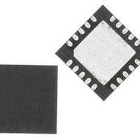
C8051F819-GM Silicon Laboratories Inc, C8051F819-GM Datasheet - Page 4

C8051F819-GM
Manufacturer Part Number
C8051F819-GM
Description
IC MCU 8BIT 8KB FLASH 20QFN
Manufacturer
Silicon Laboratories Inc
Series
C8051F81xr
Datasheet
1.C8051F800DK.pdf
(250 pages)
Specifications of C8051F819-GM
Core Processor
8051
Core Size
8-Bit
Speed
25MHz
Connectivity
SMBus (2-Wire/I²C), SPI, UART/USART
Peripherals
Cap Sense, POR, PWM, WDT
Number Of I /o
17
Program Memory Size
8KB (8K x 8)
Program Memory Type
FLASH
Ram Size
512 x 8
Voltage - Supply (vcc/vdd)
1.8 V ~ 3.6 V
Oscillator Type
Internal
Operating Temperature
-40°C ~ 85°C
Package / Case
20-QFN
Processor Series
C8051F8x
Core
8051
Data Bus Width
16 bit
Data Ram Size
512 B
Interface Type
I2C, SPI, UART
Maximum Clock Frequency
25 MHz
Number Of Programmable I/os
17
Number Of Timers
3
Operating Supply Voltage
1.8 V to 3.6 V
Maximum Operating Temperature
+ 125 C
Mounting Style
SMD/SMT
3rd Party Development Tools
PK51, CA51, A51, ULINK2
Development Tools By Supplier
C8051F800DK
Minimum Operating Temperature
- 55 C
Package
20QFN EP
Device Core
8051
Family Name
C8051F8xx
Maximum Speed
25 MHz
Lead Free Status / RoHS Status
Lead free / RoHS Compliant
Eeprom Size
-
Data Converters
-
Lead Free Status / Rohs Status
Details
Other names
336-1799-5
C8051F80x-83x
16. In-System Device Identification............................................................................ 95
17. Special Function Registers................................................................................... 97
18. Interrupts .............................................................................................................. 102
19. Flash Memory....................................................................................................... 113
20. Power Management Modes................................................................................. 120
21. Reset Sources ...................................................................................................... 123
22. Oscillators and Clock Selection ......................................................................... 129
23. Port Input/Output ................................................................................................. 138
4
15.2. Data Memory ................................................................................................... 93
18.1. MCU Interrupt Sources and Vectors.............................................................. 103
18.2. Interrupt Register Descriptions ...................................................................... 104
18.3. INT0 and INT1 External Interrupts................................................................. 111
19.1. Programming The Flash Memory .................................................................. 113
19.2. Non-volatile Data Storage ............................................................................. 114
19.3. Security Options ............................................................................................ 114
19.4. Flash Write and Erase Guidelines ................................................................. 115
20.1. Idle Mode....................................................................................................... 120
20.2. Stop Mode ..................................................................................................... 121
20.3. Suspend Mode .............................................................................................. 121
21.1. Power-On Reset ............................................................................................ 124
21.2. Power-Fail Reset / VDD Monitor ................................................................... 125
21.3. External Reset ............................................................................................... 126
21.4. Missing Clock Detector Reset ....................................................................... 126
21.5. Comparator0 Reset ....................................................................................... 127
21.6. PCA Watchdog Timer Reset ......................................................................... 127
21.7. Flash Error Reset .......................................................................................... 127
21.8. Software Reset .............................................................................................. 127
22.1. System Clock Selection................................................................................. 129
22.2. Programmable Internal High-Frequency (H-F) Oscillator .............................. 131
22.3. External Oscillator Drive Circuit..................................................................... 133
15.2.1. Internal RAM ........................................................................................... 93
18.1.1. Interrupt Priorities.................................................................................. 103
18.1.2. Interrupt Latency ................................................................................... 103
19.1.1. Flash Lock and Key Functions .............................................................. 113
19.1.2. Flash Erase Procedure ......................................................................... 113
19.1.3. Flash Write Procedure .......................................................................... 114
19.4.1. VDD Maintenance and the VDD Monitor .............................................. 116
19.4.2. PSWE Maintenance .............................................................................. 116
19.4.3. System Clock ........................................................................................ 117
22.3.1. External Crystal Example...................................................................... 135
22.3.2. External RC Example............................................................................ 136
22.3.3. External Capacitor Example.................................................................. 137
15.2.1.1. General Purpose Registers ............................................................ 94
15.2.1.2. Bit Addressable Locations .............................................................. 94
15.2.1.3. Stack ............................................................................................ 94
Rev. 1.0


