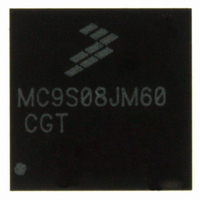
MC9S08JM60CGT Freescale Semiconductor, MC9S08JM60CGT Datasheet - Page 130

MC9S08JM60CGT
Manufacturer Part Number
MC9S08JM60CGT
Description
IC MCU 8BIT 60K FLASH 48-QFN
Manufacturer
Freescale Semiconductor
Series
HCS08r
Datasheet
1.MC9S08JM32CLD.pdf
(388 pages)
Specifications of MC9S08JM60CGT
Core Processor
HCS08
Core Size
8-Bit
Speed
48MHz
Connectivity
I²C, LIN, SCI, SPI, USB
Peripherals
LVD, POR, PWM, WDT
Number Of I /o
37
Program Memory Size
60KB (60K x 8)
Program Memory Type
FLASH
Ram Size
4K x 8
Voltage - Supply (vcc/vdd)
2.7 V ~ 5.5 V
Data Converters
A/D 8x12b
Oscillator Type
External
Operating Temperature
-40°C ~ 85°C
Package / Case
48-QFN
Processor Series
S08JM
Core
HCS08
Data Bus Width
8 bit
Data Ram Size
4 KB
Interface Type
SCI/SPI
Maximum Clock Frequency
24 MHz
Number Of Programmable I/os
37
Number Of Timers
8
Maximum Operating Temperature
+ 85 C
Mounting Style
SMD/SMT
3rd Party Development Tools
EWS08
Development Tools By Supplier
DEMOJM, DEMOJMSKT, DEMOFLEXISJMSD, DEMO9S08JM16
Minimum Operating Temperature
- 40 C
On-chip Adc
8-ch x 12-bit
Cpu Family
HCS08
Device Core Size
8b
Frequency (max)
24MHz
Total Internal Ram Size
4KB
# I/os (max)
37
Number Of Timers - General Purpose
8
Operating Supply Voltage (typ)
3.3/5V
Operating Supply Voltage (max)
5.5V
Operating Supply Voltage (min)
2.7V
Instruction Set Architecture
CISC
Operating Temp Range
-40C to 85C
Operating Temperature Classification
Industrial
Mounting
Surface Mount
Pin Count
48
Package Type
QFN EP
Package
48QFN EP
Family Name
HCS08
Maximum Speed
24 MHz
Operating Supply Voltage
3.3|5 V
For Use With
DEMOJM - KIT DEMO FOR JM MCU FAMILYDEMOJMSKT - BOARD DEMO S08JM CARD W/SOCKET
Lead Free Status / RoHS Status
Lead free / RoHS Compliant
Eeprom Size
-
Lead Free Status / Rohs Status
Lead free / RoHS Compliant
Available stocks
Company
Part Number
Manufacturer
Quantity
Price
- Current page: 130 of 388
- Download datasheet (5Mb)
Keyboard Interrupts (S08KBIV2)
9.2
The KBI input pins can be used to detect either falling edges, or both falling edge and low level interrupt
requests. The KBI input pins can also be used to detect either rising edges, or both rising edge and high
level interrupt requests.
The signal properties of KBI are shown in
9.3
The KBI includes three registers:
Refer to the direct-page register summary in the
all KBI registers. This section refers to registers and control bits only by their names.
Some MCUs may have more than one KBI, so register names include placeholder characters to identify
which KBI is being referenced.
9.3.1
KBISC contains the status flag and control bits, which are used to configure the KBI.
130
KBIP0
KBIPn
KBEDG0
KBEDGn
•
•
•
An 8-bit pin status and control register.
An 8-bit pin enable register.
An 8-bit edge select register.
External Signal Description
Register Definition
0
0
1
1
S
S
KBI Status and Control Register (KBISC)
KBIPE0
KBIPEn
Signal
KBIPn
MC9S08JM60 Series Data Sheet, Rev. 3
Figure 9-2. KBI Block Diagram
Keyboard interrupt pins
Table 9-1. Signal Properties
KBMOD
Table
V
DD
Memory
9-1.
D
CK
Function
CLR
Q
chapter for the absolute address assignments for
INTERRUPT FF
KEYBOARD
KBACK
RESET
STOP
I/O
SYNCHRONIZER
STOP BYPASS
I
BUSCLK
KBIE
Freescale Semiconductor
KBF
KBI
INTERRUPT
REQUES
T
Related parts for MC9S08JM60CGT
Image
Part Number
Description
Manufacturer
Datasheet
Request
R
Part Number:
Description:
Manufacturer:
Freescale Semiconductor, Inc
Datasheet:
Part Number:
Description:
Manufacturer:
Freescale Semiconductor, Inc
Datasheet:
Part Number:
Description:
Manufacturer:
Freescale Semiconductor, Inc
Datasheet:
Part Number:
Description:
Manufacturer:
Freescale Semiconductor, Inc
Datasheet:
Part Number:
Description:
Manufacturer:
Freescale Semiconductor, Inc
Datasheet:
Part Number:
Description:
Manufacturer:
Freescale Semiconductor, Inc
Datasheet:
Part Number:
Description:
Manufacturer:
Freescale Semiconductor, Inc
Datasheet:
Part Number:
Description:
Manufacturer:
Freescale Semiconductor, Inc
Datasheet:
Part Number:
Description:
Manufacturer:
Freescale Semiconductor, Inc
Datasheet:
Part Number:
Description:
Manufacturer:
Freescale Semiconductor, Inc
Datasheet:
Part Number:
Description:
Manufacturer:
Freescale Semiconductor, Inc
Datasheet:
Part Number:
Description:
Manufacturer:
Freescale Semiconductor, Inc
Datasheet:
Part Number:
Description:
Manufacturer:
Freescale Semiconductor, Inc
Datasheet:
Part Number:
Description:
Manufacturer:
Freescale Semiconductor, Inc
Datasheet:
Part Number:
Description:
Manufacturer:
Freescale Semiconductor, Inc
Datasheet:


