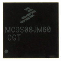
MC9S08JM60CGT Freescale Semiconductor, MC9S08JM60CGT Datasheet - Page 321

MC9S08JM60CGT
Manufacturer Part Number
MC9S08JM60CGT
Description
IC MCU 8BIT 60K FLASH 48-QFN
Manufacturer
Freescale Semiconductor
Series
HCS08r
Datasheet
1.MC9S08JM32CLD.pdf
(388 pages)
Specifications of MC9S08JM60CGT
Core Processor
HCS08
Core Size
8-Bit
Speed
48MHz
Connectivity
I²C, LIN, SCI, SPI, USB
Peripherals
LVD, POR, PWM, WDT
Number Of I /o
37
Program Memory Size
60KB (60K x 8)
Program Memory Type
FLASH
Ram Size
4K x 8
Voltage - Supply (vcc/vdd)
2.7 V ~ 5.5 V
Data Converters
A/D 8x12b
Oscillator Type
External
Operating Temperature
-40°C ~ 85°C
Package / Case
48-QFN
Processor Series
S08JM
Core
HCS08
Data Bus Width
8 bit
Data Ram Size
4 KB
Interface Type
SCI/SPI
Maximum Clock Frequency
24 MHz
Number Of Programmable I/os
37
Number Of Timers
8
Maximum Operating Temperature
+ 85 C
Mounting Style
SMD/SMT
3rd Party Development Tools
EWS08
Development Tools By Supplier
DEMOJM, DEMOJMSKT, DEMOFLEXISJMSD, DEMO9S08JM16
Minimum Operating Temperature
- 40 C
On-chip Adc
8-ch x 12-bit
Cpu Family
HCS08
Device Core Size
8b
Frequency (max)
24MHz
Total Internal Ram Size
4KB
# I/os (max)
37
Number Of Timers - General Purpose
8
Operating Supply Voltage (typ)
3.3/5V
Operating Supply Voltage (max)
5.5V
Operating Supply Voltage (min)
2.7V
Instruction Set Architecture
CISC
Operating Temp Range
-40C to 85C
Operating Temperature Classification
Industrial
Mounting
Surface Mount
Pin Count
48
Package Type
QFN EP
Package
48QFN EP
Family Name
HCS08
Maximum Speed
24 MHz
Operating Supply Voltage
3.3|5 V
For Use With
DEMOJM - KIT DEMO FOR JM MCU FAMILYDEMOJMSKT - BOARD DEMO S08JM CARD W/SOCKET
Lead Free Status / RoHS Status
Lead free / RoHS Compliant
Eeprom Size
-
Lead Free Status / Rohs Status
Lead free / RoHS Compliant
Available stocks
Company
Part Number
Manufacturer
Quantity
Price
- Current page: 321 of 388
- Download datasheet (5Mb)
appropriate course of action for future transactions — stalling the endpoint, canceling the transfer,
disabling the endpoint, etc.
17.4.4
Packet processing for a USB device consists of managing buffers for IN (to the USB Host) and OUT (to
the USB device) transactions. Packet processing is further divided into request processing on Endpoint 0,
and data packet processing on the data endpoints.
17.4.4.1
Data pipe processing is essentially a buffer management task. The firmware is responsible for managing
the shared buffer RAM to ensure that a BD is always ready for the hardware to process (OWN bit = 1).
The device allocates buffers within the shared RAM, sets up the buffer descriptors, and waits for interrupts.
On receipt of a TOKDNE interrupt, the firmware reads the STAT register to determine which endpoint is
affected, then reads the corresponding BDT entry to determine what to do next.
When processing data packets, firmware is responsible for managing the size of the packet buffers to be
in compliance with the USB specification, and the physical limitations of this module. Packet sizes up to
64 bytes are supported on all endpoints. Isochronous endpoints also can only specify packet sizes up to 64
bytes.
Firmware is also responsible for setting the appropriate bits in the BDT. For most applications using bulk
packets (control, bulk, and interrupt-type transfers), the firmware will set the DTS, BC and EPADR fields
for each BD. For isochronous packets, firmware will set BC and EPADR fields. In all cases, firmware will
set the OWN bit to enable the endpoint for data transfers.
17.4.4.2
In most cases, commands to the USB device are directed to Endpoint 0. The host uses the “Standard
Requests” described in Chapter 9 of the USB specification to enumerate and configure the device. Class
drivers or product specific drivers running on the host send class (HID, Mass Storage, Imaging) and vendor
specific commands to the device on endpoint 0.
USB requests always follow a specific format:
Device firmware monitors the INTSTAT and STAT registers, the endpoint 0 buffer descriptors (BD’s), and
the contents of the setup packet to correctly execute the host’s request.
The flow for processing endpoint 0 requests is as follows:
Freescale Semiconductor
•
•
•
1. Allocate 8-byte buffers for endpoint 0 OUT.
Host sends a SETUP token, followed by an 8-byte setup packet, and the device hardware can send
a handshake packet.
If the setup packet specifies a data phase, the host and device may transfer up to 64 Kbytes of data
(either IN or OUT, not both).
The request is terminated by a status phase.
USB Packet Processing
USB Data Pipe Processing
Request Processing on Endpoint 0
MC9S08JM60 Series Data Sheet, Rev. 3
Universal Serial Bus Device Controller (S08USBV1)
321
Related parts for MC9S08JM60CGT
Image
Part Number
Description
Manufacturer
Datasheet
Request
R
Part Number:
Description:
Manufacturer:
Freescale Semiconductor, Inc
Datasheet:
Part Number:
Description:
Manufacturer:
Freescale Semiconductor, Inc
Datasheet:
Part Number:
Description:
Manufacturer:
Freescale Semiconductor, Inc
Datasheet:
Part Number:
Description:
Manufacturer:
Freescale Semiconductor, Inc
Datasheet:
Part Number:
Description:
Manufacturer:
Freescale Semiconductor, Inc
Datasheet:
Part Number:
Description:
Manufacturer:
Freescale Semiconductor, Inc
Datasheet:
Part Number:
Description:
Manufacturer:
Freescale Semiconductor, Inc
Datasheet:
Part Number:
Description:
Manufacturer:
Freescale Semiconductor, Inc
Datasheet:
Part Number:
Description:
Manufacturer:
Freescale Semiconductor, Inc
Datasheet:
Part Number:
Description:
Manufacturer:
Freescale Semiconductor, Inc
Datasheet:
Part Number:
Description:
Manufacturer:
Freescale Semiconductor, Inc
Datasheet:
Part Number:
Description:
Manufacturer:
Freescale Semiconductor, Inc
Datasheet:
Part Number:
Description:
Manufacturer:
Freescale Semiconductor, Inc
Datasheet:
Part Number:
Description:
Manufacturer:
Freescale Semiconductor, Inc
Datasheet:
Part Number:
Description:
Manufacturer:
Freescale Semiconductor, Inc
Datasheet:


