MC9S08QA4CDNE Freescale Semiconductor, MC9S08QA4CDNE Datasheet - Page 6
MC9S08QA4CDNE
Manufacturer Part Number
MC9S08QA4CDNE
Description
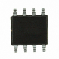
IC MCU 8BIT 4K FLASH 8-SOIC
Manufacturer
Freescale Semiconductor
Series
HCS08r
Datasheet
1.MC9S08QA2CFQE.pdf
(32 pages)
Specifications of MC9S08QA4CDNE
Core Processor
HCS08
Core Size
8-Bit
Speed
20MHz
Peripherals
LVD, POR, PWM, WDT
Number Of I /o
4
Program Memory Size
4KB (4K x 8)
Program Memory Type
FLASH
Ram Size
256 x 8
Voltage - Supply (vcc/vdd)
1.8 V ~ 3.6 V
Data Converters
A/D 4x10b
Oscillator Type
Internal
Operating Temperature
-40°C ~ 85°C
Package / Case
8-SOIC (3.9mm Width)
Processor Series
S08QA
Core
HCS08
Data Bus Width
8 bit
Data Ram Size
256 B
Interface Type
I2C, SCI, SPI
Maximum Clock Frequency
20 MHz
Number Of Programmable I/os
4
Number Of Timers
1
Operating Supply Voltage
3.6 V
Maximum Operating Temperature
+ 85 C
Mounting Style
SMD/SMT
3rd Party Development Tools
EWS08
Development Tools By Supplier
DEMO9S08QA4
Minimum Operating Temperature
- 40 C
On-chip Adc
4-ch x 10-bit
Lead Free Status / RoHS Status
Lead free / RoHS Compliant
Eeprom Size
-
Connectivity
-
Lead Free Status / Rohs Status
Lead free / RoHS Compliant


Electrical Characteristics
The average chip-junction temperature (T
where:
For most applications, P
is:
Solving
where K is a constant pertaining to the particular part. K can be determined from
for a known T
for any value of T
3.4
Although damage from electrostatic discharge (ESD) is much less common on these devices than on early CMOS circuits,
normal handling precautions should be used to avoid exposure to static discharge. Qualification tests are performed to ensure
that these devices can withstand exposure to reasonable levels of static without suffering any permanent damage.
All ESD testing is in conformity with AEC-Q100 Stress Test Qualification for Automotive Grade Integrated Circuits. During
the device qualification ESD stresses were performed for the human body model (HBM), the machine model (MM) and the
charge device model (CDM).
6
Equation 1
— T
— θ
— P
— P
— P
ESD Protection and Latch-Up Immunity
A
A
JA
D
int
I/O
. Using this value of K, the values of P
= Ambient temperature, °C
= P
= Package thermal resistance, junction-to-ambient, °C/W
= I
A
= Power dissipation on input and output pins — user-determined
.
and
int
DD
Operating temperature range
(packaged)
Thermal resistance
Thermal resistance
+ P
× V
Single-layer board
Four-layer board
I/O
Equation 2
I/O
<< P
DD
, Watts — chip internal power
8-pin PDIP
8-pin NB SOIC
8-pin DFN
8-pin PDIP
8-pin NB SOIC
8-pin DFN
int
and can be neglected. An approximate relationship between P
for K gives:
Rating
K = P
MC9S08QA4 Series MCU Data Sheet, Rev. 3
J
) in °C can be obtained from:
Table 3. Thermal Characteristics
D
P
T
× (T
D
J
= K ÷ (T
= T
A
D
+ 273°C) + θ
and T
A
+ (P
J
J
+ 273°C)
can be obtained by solving
D
Symbol
× θ
θ
θ
T
JA
JA
JA
A
JA
)
× (P
D
)
2
Equation 3
–40 to 85
T
Value
L
113
150
179
72
87
41
to T
H
Equation 1
by measuring P
D
and T
°C/W
°C/W
Unit
and
°C
Freescale Semiconductor
J
Equation 2
(if P
D
I/O
(at equilibrium)
is neglected)
iteratively
Eqn. 1
Eqn. 2
Eqn. 3
Related parts for MC9S08QA4CDNE
Image
Part Number
Description
Manufacturer
Datasheet
Request
R

Part Number:
Description:
Manufacturer:
Freescale Semiconductor, Inc
Datasheet:
Part Number:
Description:
Manufacturer:
Freescale Semiconductor, Inc
Datasheet:
Part Number:
Description:
Manufacturer:
Freescale Semiconductor, Inc
Datasheet:
Part Number:
Description:
Manufacturer:
Freescale Semiconductor, Inc
Datasheet:
Part Number:
Description:
Manufacturer:
Freescale Semiconductor, Inc
Datasheet:
Part Number:
Description:
Manufacturer:
Freescale Semiconductor, Inc
Datasheet:
Part Number:
Description:
Manufacturer:
Freescale Semiconductor, Inc
Datasheet:
Part Number:
Description:
Manufacturer:
Freescale Semiconductor, Inc
Datasheet:
Part Number:
Description:
Manufacturer:
Freescale Semiconductor, Inc
Datasheet:
Part Number:
Description:
Manufacturer:
Freescale Semiconductor, Inc
Datasheet:
Part Number:
Description:
Manufacturer:
Freescale Semiconductor, Inc
Datasheet:
Part Number:
Description:
Manufacturer:
Freescale Semiconductor, Inc
Datasheet:
Part Number:
Description:
Manufacturer:
Freescale Semiconductor, Inc
Datasheet:
Part Number:
Description:
Manufacturer:
Freescale Semiconductor, Inc
Datasheet:
Part Number:
Description:
Manufacturer:
Freescale Semiconductor, Inc
Datasheet: