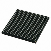
MCIMX512CJM6C Freescale Semiconductor, MCIMX512CJM6C Datasheet - Page 97

MCIMX512CJM6C
Manufacturer Part Number
MCIMX512CJM6C
Description
MULTIMEDIA PROC 529-LFBGA
Manufacturer
Freescale Semiconductor
Series
i.MX51r
Specifications of MCIMX512CJM6C
Core Processor
ARM Cortex-A8
Core Size
32-Bit
Speed
600MHz
Connectivity
1-Wire, EBI/EMI, Ethernet, I²C, IrDA, MMC, SPI, SSI, UART/USART, USB OTG
Peripherals
DMA, I²S, LCD, POR, PWM, WDT
Number Of I /o
128
Program Memory Type
ROMless
Ram Size
128K x 8
Voltage - Supply (vcc/vdd)
0.8 V ~ 1.15 V
Oscillator Type
External
Operating Temperature
-20°C ~ 85°C
Package / Case
529-LFBGA
Operating Temperature (min)
-40C
Operating Temperature Classification
Industrial
Mounting
Surface Mount
Processor Series
i.MX51
Core
ARM Cortex A8
Data Bus Width
32 bit
Program Memory Size
36 KB
Data Ram Size
128 KB
Interface Type
I2C, SPI, SSI, UART, USB
Maximum Clock Frequency
200 MHz
Number Of Timers
5
Operating Supply Voltage
0.8 V to 1.15 V
Maximum Operating Temperature
+ 95 C
Mounting Style
SMD/SMT
3rd Party Development Tools
MDK-ARM, RL-ARM, ULINK2
Development Tools By Supplier
MCIMX51EVKJ
Minimum Operating Temperature
- 40 C
Lead Free Status / RoHS Status
Lead free / RoHS Compliant
Eeprom Size
-
Program Memory Size
-
Data Converters
-
Lead Free Status / Rohs Status
Compliant
- Current page: 97 of 200
- Download datasheet (6Mb)
1
2
3
4.7.8.7
4.7.8.7.1
The IPU has four signal generator machines for asynchronous signal. Each machine generates IPU’s
internal control levels (0 or 1) by UP and DOWN are defined in Registers. Each asynchronous pin has a
dynamic connection with one of the signal generators. This connection is redefined again with a new
display access (pixel/component) The IPU can generate control signals according to system 80/68
requirements. The burst length is received as a result from predefined behavior of the internal signal
generator machines.
The access to a display is realized by the following:
Both system 80 and system 68k interfaces are supported for all described modes as depicted in
Figure
signals.
Each asynchronous access is defined by an access size parameter. This parameter can be different between
different kinds of accesses. This parameter defines a length of windows, when suitable controls of the
current access are valid. A pause between two different display accesses can be guaranteed by programing
of suitable access sizes. There are no minimal/maximal hold/setup time hard defined by DI. Each control
signal can be switched at any time during access size.
Freescale Semiconductor
Chroma/Luma Gain Inequality
Chroma/Luma Delay Inequality
VIDEO PERFORMANCE IN HD MODE
Luma Frequency Response
Chroma Frequency Response
Luma Nonlinearity
Chroma Nonlinearity
Luma Signal-to-Noise Ratio
Chroma Signal-to-Noise Ratio
Guaranteed by design
Guaranteed by characterization
R
set
•
•
•
•
= VREFOUT's external resistor to ground = 1.05 kΩ
58,
CS (IPP_CS) chip select
WR (IPP_PIN_11) write strobe
RD (IPP_PIN_12) read strobe
RS (IPP_PIN_13) Register select (A0)
Figure
Asynchronous Interfaces
Standard Parallel Interfaces
i.MX51 Applications Processors for Consumer and Industrial Products, Rev. 4
59, and
Table 82. TV Encoder Video Performance Specifications (continued)
Figure
60. The timing images correspond to active-low IPP_CS, WR and RD
2
YCbCr 422 mode
0-15 MHz,
0-30 MHz
0-30 MHz
0-15 MHz
—
—
—
—
—
–0.2
–0.2
—
—
—
—
—
—
—
1.0
1.0
3.2
3.4
—
—
—
62
72
Electrical Characteristics
0.2
0.2
—
—
—
—
—
—
—
±%
±ns
—
dB
dB
%
%
dB
dB
Figure
57,
97
Related parts for MCIMX512CJM6C
Image
Part Number
Description
Manufacturer
Datasheet
Request
R
Part Number:
Description:
MCIMX-LVDS1
Manufacturer:
Freescale Semiconductor
Datasheet:
Part Number:
Description:
Manufacturer:
Freescale Semiconductor, Inc
Datasheet:
Part Number:
Description:
Manufacturer:
Freescale Semiconductor, Inc
Datasheet:
Part Number:
Description:
Manufacturer:
Freescale Semiconductor, Inc
Datasheet:
Part Number:
Description:
Manufacturer:
Freescale Semiconductor, Inc
Datasheet:
Part Number:
Description:
Manufacturer:
Freescale Semiconductor, Inc
Datasheet:
Part Number:
Description:
Manufacturer:
Freescale Semiconductor, Inc
Datasheet:
Part Number:
Description:
Manufacturer:
Freescale Semiconductor, Inc
Datasheet:
Part Number:
Description:
Manufacturer:
Freescale Semiconductor, Inc
Datasheet:
Part Number:
Description:
Manufacturer:
Freescale Semiconductor, Inc
Datasheet:
Part Number:
Description:
Manufacturer:
Freescale Semiconductor, Inc
Datasheet:
Part Number:
Description:
Manufacturer:
Freescale Semiconductor, Inc
Datasheet:
Part Number:
Description:
Manufacturer:
Freescale Semiconductor, Inc
Datasheet:
Part Number:
Description:
Manufacturer:
Freescale Semiconductor, Inc
Datasheet:
Part Number:
Description:
Manufacturer:
Freescale Semiconductor, Inc
Datasheet:


