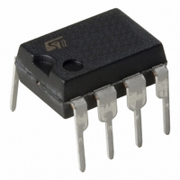
ST7FLITEU09B6 STMicroelectronics, ST7FLITEU09B6 Datasheet - Page 127

ST7FLITEU09B6
Manufacturer Part Number
ST7FLITEU09B6
Description
MCU 8BIT SGL VOLT FLASH 8-DIP
Manufacturer
STMicroelectronics
Series
ST7r
Datasheet
1.ST7FLITEU05M6.pdf
(139 pages)
Specifications of ST7FLITEU09B6
Core Processor
ST7
Core Size
8-Bit
Speed
8MHz
Peripherals
LVD, POR, PWM, WDT
Number Of I /o
5
Program Memory Size
2KB (2K x 8)
Program Memory Type
FLASH
Eeprom Size
128 x 8
Ram Size
128 x 8
Voltage - Supply (vcc/vdd)
2.4 V ~ 5.5 V
Data Converters
A/D 5x10b
Oscillator Type
Internal
Operating Temperature
-40°C ~ 85°C
Package / Case
8-DIP (0.300", 7.62mm)
Processor Series
ST7FLITEUx
Core
ST7
Data Bus Width
8 bit
Data Ram Size
128 B
Interface Type
ICC
Maximum Clock Frequency
8 MHz
Number Of Programmable I/os
5
Number Of Timers
2
Maximum Operating Temperature
+ 85 C
Mounting Style
Through Hole
Development Tools By Supplier
ST7FLITE-SK/RAIS, ST7FLITU0-D/RAIS, STX-RLINK
Minimum Operating Temperature
- 40 C
On-chip Adc
10 bit, 5 Channel
For Use With
497-5858 - EVAL BOARD PLAYBACK ST7FLITE
Lead Free Status / RoHS Status
Lead free / RoHS Compliant
Connectivity
-
Lead Free Status / Rohs Status
Details
Available stocks
Company
Part Number
Manufacturer
Quantity
Price
ST7LITEU05 ST7LITEU09
15
15.1
15.1.1
Device configuration and ordering information
Each device is available for production in user programmable versions (Flash) as well as in
factory coded versions (FASTROM).
ST7PLITEU05 and ST7PLITEU09 devices are Factory Advanced Service Technique ROM
(FASTROM) versions of ST7LITEU05 and ST7LITEU09 devices : they are factory-
programmed XFlash devices.
ST7FLITEU05 and ST7FLITEU09 XFlash devices are XFlash versions of ST7LITEU05 and
ST7LITEU09 devices. They are shipped to customers with a default program memory
content (FFh).
The FASTROM factory coded parts contain the code supplied by the customer. This implies
that Flash devices have to be configured by the customer using the Option Bytes while the
FASTROM devices are factory-configured.
Option bytes
The two option bytes allow the hardware configuration of the microcontroller to be selected.
The option bytes can be accessed only in programming mode (for example using a standard
ST7 programming tool).
Option byte 1
Bits 7:6 = CKSEL[1:0] Startup clock selection.
This bit is used to select the startup frequency. By default, the Internal RC is selected.
Table 78.
Bit 5 = Reserved, must always be 1.
Bit 4 = Reserved, must always be 0.
Bits 3:2 = LVD[1:0] Low voltage detection selection
Table 79.
These option bits enable the LVD block with a selected threshold as shown in
Startup clock selection
LVD threshold configuration
Internal RC as startup clock
AWU RC as a startup clock
External clock on pin PA5
Configuration
Medium voltage threshold
Highest voltage threshold
Lowest voltage threshold
Reserved
Configuration
LVD Off
Device configuration and ordering information
CKSEL1
0
0
1
1
LVD1
1
1
0
0
CKSEL0
Table
0
1
0
1
LVD0
127/139
1
0
1
0
79.


