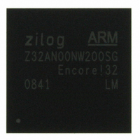
Z32AN00NW200SG Zilog, Z32AN00NW200SG Datasheet - Page 85

Z32AN00NW200SG
Manufacturer Part Number
Z32AN00NW200SG
Description
IC ARM922T MCU 200MHZ 256-BGA
Manufacturer
Zilog
Series
Encore!® 32r
Datasheet
1.Z32AN00NW200SG.pdf
(196 pages)
Specifications of Z32AN00NW200SG
Core Processor
ARM9
Core Size
16/32-Bit
Speed
200MHz
Connectivity
EBI/EMI, IrDA, SmartCard, SPI, UART/USART, USB OTG
Peripherals
DMA, LCD, Magnetic Card Reader, POR, PWM, WDT
Number Of I /o
76
Program Memory Type
ROMless
Ram Size
64K x 8
Voltage - Supply (vcc/vdd)
1.71 V ~ 3.6 V
Data Converters
A/D 4x10b
Oscillator Type
Internal
Operating Temperature
-40°C ~ 85°C
Package / Case
256-LBGA
For Use With
269-4713 - KIT DEV ENCORE 32 SERIES
Lead Free Status / RoHS Status
Lead free / RoHS Compliant
Eeprom Size
-
Program Memory Size
-
Other names
269-4717
Available stocks
Company
Part Number
Manufacturer
Quantity
Price
- Current page: 85 of 196
- Download datasheet (4Mb)
Z32AN Series Data Sheet
10.2.3 Controller
DS0200-003
There is one controller state machine in Smart Card 0 and four controller state machines in Smart Card 1 to
manage card power on, card cold and warm reset, and card deactivation stages. The Smart Card 1
multiplexer must be configured before each command to select the appropriate controller state machine via
SIM_SEL. The state diagram for the controller is shown below.
The states are described below:
Idle: After card detection (DET_CMD), software sets COMMAND.PWR_CARD to ‘1’ to power
up the card before changing to PowerCard. All outputs are in their inactive state.
PowerCard: The controller applies power. Software sets COMMAND.DEAC_CARD to ‘1’. It
is up to software to ensure power is stable before sending the CardReset command by reading
SCSTATUS. If the card is removed, the controller automatically returns to the Idle state.
ResetCard: On entering this state, the card clock is started, the card IO is ‘0’, the card reset is
asserted by the external interface device, and the reset duration counter is started. When the
counter reaches the count programmed in RST_LEN, the controller changes to
WaitCommand. If the card is removed anytime during the reset state the controller changes to
WaitDeactivation.
WaitCommand: On entering this state, card reset is set inactive and data transfers may occur.
When data transfer is complete, one of the following three commands can be issued.
o
o
o
If the card is removed during this state the controller automatically changes to the
WaitDeactivation state.
WaitDeactivation: On entering this state, the deactivation delay counter is started. When the
counter reaches the count programmed in DEAC_DLY, the controller moves to
DeacResetCard. It is up to the software to program the proper delay according to the protocol
or the current card session stage.
DeacResetCard: The external interface card reset is pulled ‘0’ and the controller moves to
DeacStopClock.
StopCardClock: The Smart Card clock is stopped.
DeactivateCard: The controller changes to WaitDeactivation.
ResetCard: The controller performs a warm reset of the card by changing to ResetCard.
Figure 10-2: State Diagram for Smart Card Controller
Page 72
Related parts for Z32AN00NW200SG
Image
Part Number
Description
Manufacturer
Datasheet
Request
R

Part Number:
Description:
Communication Controllers, ZILOG INTELLIGENT PERIPHERAL CONTROLLER (ZIP)
Manufacturer:
Zilog, Inc.
Datasheet:

Part Number:
Description:
KIT DEV FOR Z8 ENCORE 16K TO 64K
Manufacturer:
Zilog
Datasheet:

Part Number:
Description:
KIT DEV Z8 ENCORE XP 28-PIN
Manufacturer:
Zilog
Datasheet:

Part Number:
Description:
DEV KIT FOR Z8 ENCORE 8K/4K
Manufacturer:
Zilog
Datasheet:

Part Number:
Description:
KIT DEV Z8 ENCORE XP 28-PIN
Manufacturer:
Zilog
Datasheet:

Part Number:
Description:
DEV KIT FOR Z8 ENCORE 4K TO 8K
Manufacturer:
Zilog
Datasheet:

Part Number:
Description:
CMOS Z8 microcontroller. ROM 16 Kbytes, RAM 256 bytes, speed 16 MHz, 32 lines I/O, 3.0V to 5.5V
Manufacturer:
Zilog, Inc.
Datasheet:

Part Number:
Description:
Low-cost microcontroller. 512 bytes ROM, 61 bytes RAM, 8 MHz
Manufacturer:
Zilog, Inc.
Datasheet:

Part Number:
Description:
Z8 4K OTP Microcontroller
Manufacturer:
Zilog, Inc.
Datasheet:

Part Number:
Description:
CMOS SUPER8 ROMLESS MCU
Manufacturer:
Zilog, Inc.
Datasheet:

Part Number:
Description:
SL1866 CMOSZ8 OTP Microcontroller
Manufacturer:
Zilog, Inc.
Datasheet:

Part Number:
Description:
SL1866 CMOSZ8 OTP Microcontroller
Manufacturer:
Zilog, Inc.
Datasheet:

Part Number:
Description:
OTP (KB) = 1, RAM = 125, Speed = 12, I/O = 14, 8-bit Timers = 2, Comm Interfaces Other Features = Por, LV Protect, Voltage = 4.5-5.5V
Manufacturer:
Zilog, Inc.
Datasheet:

Part Number:
Description:
Manufacturer:
Zilog, Inc.
Datasheet:


