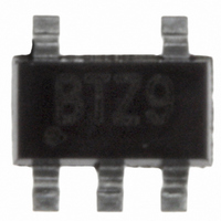
EL8103IWZ-T7A Intersil, EL8103IWZ-T7A Datasheet - Page 11

EL8103IWZ-T7A
Manufacturer Part Number
EL8103IWZ-T7A
Description
IC OPAMP 500MHZ R-R SOT23-5
Manufacturer
Intersil
Datasheet
1.EL8103IWZ-T7A.pdf
(14 pages)
Specifications of EL8103IWZ-T7A
Amplifier Type
Voltage Feedback
Number Of Circuits
1
Output Type
Rail-to-Rail
Slew Rate
600 V/µs
Gain Bandwidth Product
200MHz
-3db Bandwidth
500MHz
Current - Input Bias
6µA
Voltage - Input Offset
800µV
Current - Supply
5.6mA
Current - Output / Channel
65mA
Voltage - Supply, Single/dual (±)
3 V ~ 5 V, ±1.5 V ~ 2.5 V
Operating Temperature
-40°C ~ 85°C
Mounting Type
Surface Mount
Package / Case
SOT-23-5, SC-74A, SOT-25
Lead Free Status / RoHS Status
Lead free / RoHS Compliant
Other names
EL8103IWZ-T7A
EL8103IWZ-T7ATR
EL8103IWZ-T7ATR
Available stocks
Company
Part Number
Manufacturer
Quantity
Price
Company:
Part Number:
EL8103IWZ-T7A
Manufacturer:
Intersil
Quantity:
500
Part Number:
EL8103IWZ-T7A
Manufacturer:
INTERSIL
Quantity:
20 000
Typical Applications
VIDEO SYNC PULSE REMOVER
Many CMOS analog to digital converters have a parasitic
latch up problem when subjected to negative input voltage
levels. Since the sync tip contains no useful video
information and it is a negative going pulse, we can chop it
off. Figure 30 shows a gain of 2 connections for EL8102,
EL8103. Figure 31 shows the complete input video signal
applied at the input, as well as the output signal with the
negative going sync pulse removed.
MULTIPLEXER
Besides the normal power-down usage, the ENABLE pin of
the EL8102 can be used for multiplexing applications. Figure
32 shows two EL8102 with the outputs tied together, driving
a back terminated 75Ω video load. A 2V
is applied to Amp A and a 1V
to Amp B. Figure 33 shows the ENABLE signal and the
resulting output waveform at V
before-make operation of the multiplexing. Amp A is on and
V
signal is low and turns off in about 25ns when the ENABLE
signal is high. About 200ns later, Amp B turns on and V
passed through to the output. The break-before-make
operation ensures that more than one amplifier isn’t trying to
drive the bus at the same time.
IN1
V
IN
is passed through to the output when the ENABLE
75Ω
FIGURE 30. SYNC PULSE REMOVER
1k
FIGURE 31. VIDEO SIGNAL
V
OUT
+
-
V
1k
5V
IN
M = 10µs/DIV
V
V
S+
S-
11
P-P
OUT
2MHz sine wave is applied
75Ω
. Observe the break-
P-P
2MHz sine wave
75Ω
1V
0.5V
0V
1V
0.5V
0V
V
EL8102, EL8103
OUT
IN2
is
SINGLE SUPPLY VIDEO LINE DRIVER
The EL8102 and EL8103 are wideband rail-to-rail output op
amplifiers with large output current, excellent dG, dP, and low
distortion that allow them to drive video signals in low supply
applications. Figure 34 is the single supply non-inverting
video line driver configuration and Figure 35 is the inverting
video line driver configuration. The signal is AC coupled by
C
provide the largest output swing. R
C
termination resistors for the line. C
big enough to minimize the droop of the luminance signal.
B
A
1
2
. R
2MHz
2MHz
1V
2V
isolates the virtual ground potential. R
P-P
P-P
1
ENABLE
and R
75Ω
75Ω
FIGURE 32. TWO TO ONE MULTIPLEXER
2
1k
1k
are used to level shift the input and output to
A
ENABLE
+
-
+
-
FIGURE 33.
+2.5V
-2.5V
+2.5V
-2.5V
1k
1k
M = 50ns/DIV
1
F
, C
and R
2
75Ω
and C
B
T
G
and R
set the AC gain.
3
-0.5V
-1.5V
-2.5V
are selected
-1V
0V
1V
0V
3
August 10, 2007
are the
FN7104.7
V
75Ω
OUT


