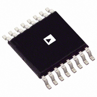
AD8370AREZ Analog Devices Inc, AD8370AREZ Datasheet - Page 14

AD8370AREZ
Manufacturer Part Number
AD8370AREZ
Description
IC AMP VGA DIFF LN 16TSSOP
Manufacturer
Analog Devices Inc
Type
Var Gain Ampr
Datasheet
1.AD8370AREZ-RL7.pdf
(28 pages)
Specifications of AD8370AREZ
Amplifier Type
Variable Gain
Number Of Circuits
1
Output Type
Differential
Slew Rate
5750 V/ns
-3db Bandwidth
750MHz
Current - Input Bias
400pA
Current - Supply
79mA
Voltage - Supply, Single/dual (±)
3 V ~ 5.5 V
Operating Temperature
-40°C ~ 85°C
Mounting Type
Surface Mount
Package / Case
16-TSSOP Exposed Pad, 16-eTSSOP, 16-HTSSOP
No. Of Amplifiers
1
Bandwidth
750MHz
No. Of Channels
1
Supply Voltage Range
3V To 5.5V
Amplifier Case Style
TSSOP
No. Of Pins
16
Operating Temperature Range
-40°C To +85°C
Number Of Channels
1
Number Of Elements
2
Power Supply Requirement
Single
Common Mode Rejection Ratio
77dB
Voltage Gain Db
34dB
Input Resistance
0.0002@5VMohm
Input Bias Current
0.9@5VnA
Single Supply Voltage (typ)
5V
Dual Supply Voltage (typ)
Not RequiredV
Power Dissipation
575mW
Rail/rail I/o Type
No
Single Supply Voltage (min)
3V
Single Supply Voltage (max)
5.5V
Dual Supply Voltage (min)
Not RequiredV
Dual Supply Voltage (max)
Not RequiredV
Operating Temp Range
-40C to 85C
Operating Temperature Classification
Industrial
Mounting
Surface Mount
Pin Count
16
Package Type
TSSOP EP
Lead Free Status / RoHS Status
Lead free / RoHS Compliant
Current - Output / Channel
-
Gain Bandwidth Product
-
Voltage - Input Offset
-
Lead Free Status / Rohs Status
Compliant
Available stocks
Company
Part Number
Manufacturer
Quantity
Price
Company:
Part Number:
AD8370AREZ
Manufacturer:
ADI
Quantity:
1 636
Part Number:
AD8370AREZ
Manufacturer:
ADI/亚德诺
Quantity:
20 000
Part Number:
AD8370AREZ-REEL7
Manufacturer:
ADI/亚德诺
Quantity:
20 000
Company:
Part Number:
AD8370AREZ-RL7
Manufacturer:
AD
Quantity:
735
Part Number:
AD8370AREZ-RL7
Manufacturer:
ADI/亚德诺
Quantity:
20 000
AD8370
OUTPUT AMPLIFIER
The output impedance is approximately 100 Ω differential and,
like the input preamplifier, this impedance is formed using
active circuit elements. See Figure 40 for a simplified schematic
of the output interface.
The gain of the output amplifier, and thus the AD8370 as a
whole, is load dependent. The following equation can be used to
predict the gain deviation of the AD8370 from that at 100 Ω as
the load is varied.
For example, if R
above that at 100 Ω, all other things being equal. If R
Ω, the gain is a factor of 0.669 (3.49 dB) below that at 100 Ω.
DIGITAL INTERFACE AND TIMING
The digital control port uses a standard TTL interface. The 8-bit
control word is read in a serial fashion when the LTCH pin is
held low. The levels presented to the DATA pin are read on each
rising edge of the CLCK signal. Figure 41 illustrates the timing
diagram for the control interface. Minimum values for timing
parameters are presented in Table 4. Figure 42 is a simplified
schematic of the digital input pins.
(PIN 14)
(PIN 13)
(PIN 12)
DATA
CLCK
LTCH
GainDeviat
T
T
DS
ES
MSB
VCC/2
Figure 40. OPHI/OPLO Simplified Circuit
ion
LOAD
MSB-1 MSB-2 MSB-3
Figure 41. Digital Timing Diagram
=
740Ω
is 1 kΩ, the gain is a factor of 1.80 (5.12 dB)
1
+
1
R
.
98
LOAD
98
T
CK
LSB+3
T
LSB+2
PW
OPHI/OPLO
LSB+1
LOAD
LSB
T
EH
is 50
Rev. A | Page 14 of 28
Table 4. Serial Programming Timing Parameters
Parameter
Clock Pulse Width (T
Clock Period (T
Setup Time Data vs. Clock (T
Setup Time Latch vs. Clock (T
Hold Time Latch vs. Clock (T
Figure 43. Simplified Circuit for VOCM Output
Figure 42. Simplified Circuit for Digital Inputs
VCC/2
CK
CLCK/DATA/LTCH/PWUP
)
PW
)
EH
DS
ES
)
)
)
75Ω
10μA
VOCM
Min
25
50
10
20
10
Unit
ns
ns
ns
ns
ns


