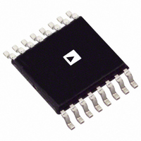
AD8370AREZ Analog Devices Inc, AD8370AREZ Datasheet - Page 22

AD8370AREZ
Manufacturer Part Number
AD8370AREZ
Description
IC AMP VGA DIFF LN 16TSSOP
Manufacturer
Analog Devices Inc
Type
Var Gain Ampr
Datasheet
1.AD8370AREZ-RL7.pdf
(28 pages)
Specifications of AD8370AREZ
Amplifier Type
Variable Gain
Number Of Circuits
1
Output Type
Differential
Slew Rate
5750 V/ns
-3db Bandwidth
750MHz
Current - Input Bias
400pA
Current - Supply
79mA
Voltage - Supply, Single/dual (±)
3 V ~ 5.5 V
Operating Temperature
-40°C ~ 85°C
Mounting Type
Surface Mount
Package / Case
16-TSSOP Exposed Pad, 16-eTSSOP, 16-HTSSOP
No. Of Amplifiers
1
Bandwidth
750MHz
No. Of Channels
1
Supply Voltage Range
3V To 5.5V
Amplifier Case Style
TSSOP
No. Of Pins
16
Operating Temperature Range
-40°C To +85°C
Number Of Channels
1
Number Of Elements
2
Power Supply Requirement
Single
Common Mode Rejection Ratio
77dB
Voltage Gain Db
34dB
Input Resistance
0.0002@5VMohm
Input Bias Current
0.9@5VnA
Single Supply Voltage (typ)
5V
Dual Supply Voltage (typ)
Not RequiredV
Power Dissipation
575mW
Rail/rail I/o Type
No
Single Supply Voltage (min)
3V
Single Supply Voltage (max)
5.5V
Dual Supply Voltage (min)
Not RequiredV
Dual Supply Voltage (max)
Not RequiredV
Operating Temp Range
-40C to 85C
Operating Temperature Classification
Industrial
Mounting
Surface Mount
Pin Count
16
Package Type
TSSOP EP
Lead Free Status / RoHS Status
Lead free / RoHS Compliant
Current - Output / Channel
-
Gain Bandwidth Product
-
Voltage - Input Offset
-
Lead Free Status / Rohs Status
Compliant
Available stocks
Company
Part Number
Manufacturer
Quantity
Price
Company:
Part Number:
AD8370AREZ
Manufacturer:
ADI
Quantity:
1 636
Part Number:
AD8370AREZ
Manufacturer:
ADI/亚德诺
Quantity:
20 000
Part Number:
AD8370AREZ-REEL7
Manufacturer:
ADI/亚德诺
Quantity:
20 000
Company:
Part Number:
AD8370AREZ-RL7
Manufacturer:
AD
Quantity:
735
Part Number:
AD8370AREZ-RL7
Manufacturer:
ADI/亚德诺
Quantity:
20 000
AD8370
EVALUATION BOARD AND SOFTWARE
The evaluation board allows quick testing of the AD8370 by
using standard 50 Ω test equipment. The schematic is shown in
Figure 59. Transformers T1 and T2 are used to transform 50 Ω
source and load impedances to the desired input and output
reference levels. The top and bottom layers are shown in
Figure 63 and Figure 64. The ground plane was removed under
the traces between T1 and Pins INHI and INLO to approximate
a 100 Ω characteristic impedance.
IN+
IN–
50Ω Tx LINE
50Ω Tx LINE
PWUP
VOCM
R8 49.9Ω
C10 OPEN
TC4-1W
R1
0Ω
P2
1:4
T1
1
1
Figure 59. AD8370 Evaluation Board Schematic
14
1nF
1nF
C1
C2
R2
0Ω
2
2
R9
OPEN
15
0.1μF
16
3
3
1
AD8370
C5
16
SW1
15
4
2
1kΩ
4
R7
17
V
Rev. A | Page 22 of 28
S
14
5
3
1kΩ
5
R6
18
0.1μF
13
6
4
C7
1kΩ
R5
19
12
7
5
20
D-SUB 25 PIN MALE
C9
11
8
6
21
GND
C6
1μF
The evaluation board comes with the AD8370 control software
that allows serial gain control from most computers. The
evaluation board is connected via a cable to the parallel port of
the computer. Adjusting the appropriate slider bar in the control
software automatically updates the gain code of the AD8370 in
either a linear or linear-in-dB fashion.
10
OPEN
7
9
C8
0.1μF
*EMI SUPPRESSION FERRITE
HZ1206E601R-00
22
10
9
8
23
1nF
1nF
C3
C4
11
R4
0Ω
L1*
+V
GND
24
S
12
25
2:1
T2
L2*
13
JTX-2-10T
R3
0Ω
50Ω Tx LINE
50Ω Tx LINE
OUT+
OUT–


