EL5108IW-T7A Intersil, EL5108IW-T7A Datasheet - Page 12
EL5108IW-T7A
Manufacturer Part Number
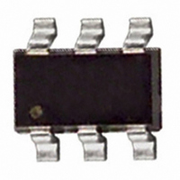
EL5108IW-T7A
Description
IC AMP FGA SGL 450MHZ SOT-23-6
Manufacturer
Intersil
Datasheet
1.EL5308IUZ-T7.pdf
(12 pages)
Specifications of EL5108IW-T7A
Amplifier Type
General Purpose
Number Of Circuits
1
Slew Rate
4500 V/µs
-3db Bandwidth
450MHz
Current - Input Bias
2µA
Voltage - Input Offset
3000µV
Current - Supply
3.7mA
Current - Output / Channel
135mA
Voltage - Supply, Single/dual (±)
5 V ~ 12 V, ±2.5 V ~ 6 V
Operating Temperature
-40°C ~ 85°C
Mounting Type
Surface Mount
Package / Case
SOT-23-6
Lead Free Status / RoHS Status
Contains lead / RoHS non-compliant
Output Type
-
Gain Bandwidth Product
-


Quarter Size Outline Plastic Packages Family (QSOP)
Intersil products are sold by description only. Intersil Corporation reserves the right to make changes in circuit design, software and/or specifications at any time without
notice. Accordingly, the reader is cautioned to verify that data sheets are current before placing orders. Information furnished by Intersil is believed to be accurate and
reliable. However, no responsibility is assumed by Intersil or its subsidiaries for its use; nor for any infringements of patents or other rights of third parties which may result
from its use. No license is granted by implication or otherwise under any patent or patent rights of Intersil or its subsidiaries.
SEATING
PLANE
0.004 C
C
E
A2
0.010
A1
E1
All Intersil U.S. products are manufactured, assembled and tested utilizing ISO9000 quality systems.
A
c
SEE DETAIL "X"
B
L1
Intersil Corporation’s quality certifications can be viewed at www.intersil.com/design/quality
C A B
DETAIL X
N
1
For information regarding Intersil Corporation and its products, see www.intersil.com
PIN #1
I.D. MARK
0.007
12
L
D
GAUGE
PLANE
e
C A B
4°±4°
0.010
A
(N/2)+1
(N/2)
b
H
EL5108, EL5308
MDP0040
QUARTER SIZE OUTLINE PLASTIC PACKAGES FAMILY
NOTES:
SYMBOL
1. Plastic or metal protrusions of 0.006” maximum per side are not
2. Plastic interlead protrusions of 0.010” maximum per side are not
3. Dimensions “D” and “E1” are measured at Datum Plane “H”.
4. Dimensioning and tolerancing per ASME Y14.5M-1994.
A1
A2
E1
L1
included.
included.
A
D
E
N
b
c
e
L
QSOP16 QSOP24 QSOP28
0.068
0.006
0.056
0.010
0.008
0.193
0.236
0.154
0.025
0.025
0.041
16
INCHES
0.068
0.006
0.056
0.010
0.008
0.341
0.236
0.154
0.025
0.025
0.041
24
0.068
0.006
0.056
0.010
0.008
0.390
0.236
0.154
0.025
0.025
0.041
28
TOLERANCE NOTES
Reference
±0.002
±0.004
±0.002
±0.001
±0.004
±0.008
±0.004
±0.009
Basic
Basic
Max.
August 10, 2010
Rev. F 2/07
FN7358.7
1, 3
2, 3
-
-
-
-
-
-
-
-
-
-
Related parts for EL5108IW-T7A
Image
Part Number
Description
Manufacturer
Datasheet
Request
R

Part Number:
Description:
IC OP AMP HS VF 450MHZ SOT23-6
Manufacturer:
Intersil
Datasheet:

Part Number:
Description:
450mhz Fixed Gain Amplifiers With Enable
Manufacturer:
Intersil Corporation
Datasheet:
Part Number:
Description:
Intersil Corporation [CMOS Serial Controller Interface]
Manufacturer:
Intersil Corporation
Datasheet:
Part Number:
Description:
Manufacturer:
Intersil Corporation
Datasheet:
Part Number:
Description:
357-036-542-201 CARDEDGE 36POS DL .156 BLK LOPRO
Manufacturer:
Intersil Corporation
Datasheet:
Part Number:
Description:
1024-Word x 4-Bit LSI Static RAM
Manufacturer:
Intersil Corporation
Datasheet:
Part Number:
Description:
General Purpose NPN Transistor Arrays FN341.4
Manufacturer:
Intersil Corporation
Datasheet:
Part Number:
Description:
CMOS 16-Bit Microprocessor
Manufacturer:
Intersil Corporation
Datasheet:
Part Number:
Description:
Manufacturer:
Intersil Corporation
Datasheet:
Part Number:
Description:
Manufacturer:
Intersil Corporation
Datasheet:
Part Number:
Description:
Manufacturer:
Intersil Corporation
Datasheet:
Part Number:
Description:
Manufacturer:
Intersil Corporation
Datasheet:
Part Number:
Description:
CMOS 6-Bit Latch and Decoder Memory Interfaces
Manufacturer:
Intersil Corporation
Datasheet:
Part Number:
Description:
CA3046General Purpose NPN Transistor Arrays
Manufacturer:
Intersil Corporation
Datasheet:
Part Number:
Description:
Manufacturer:
Intersil Corporation
Datasheet: