X40431S14I-A Intersil, X40431S14I-A Datasheet - Page 8

X40431S14I-A
Manufacturer Part Number
X40431S14I-A
Description
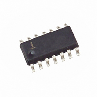
IC VOLT MON TRPL EEPROM 14-SOIC
Manufacturer
Intersil
Type
Multi-Voltage Supervisorr
Datasheet
1.X40430S14Z-A.pdf
(26 pages)
Specifications of X40431S14I-A
Number Of Voltages Monitored
3
Output
Open Drain or Open Collector
Reset
Active Low
Reset Timeout
Adjustable/Selectable
Voltage - Threshold
1.7V, 2.9V, 4.6V
Operating Temperature
-40°C ~ 85°C
Mounting Type
Surface Mount
Package / Case
14-SOIC (3.9mm Width), 14-SOL
Lead Free Status / RoHS Status
Contains lead / RoHS non-compliant
Available stocks
Company
Part Number
Manufacturer
Quantity
Price
Company:
Part Number:
X40431S14I-A
Manufacturer:
Intersil
Quantity:
500
Figure 2. Two Uses of Multiple Voltage Monitoring
Figure 3. V
WATCHDOG TIMER
The Watchdog Timer circuit monitors the microproces-
sor activity by monitoring the SDA and SCL pins. A
standard read or write sequence to any slave address
byte restarts the watchdog timer and prevents the
WDO signal going active. A minimum sequence to
reset the watchdog timer requires four microprocessor
instructions namely, a Start, Clock Low, Clock High
and Stop. The state of two nonvolatile control bits in
the Status Register determine the watchdog timer
period. The microprocessor can change these watch-
dog bits by writing to the X40430, X40431, X40434,
X40435 control register (also refer to page 20).
Notice: No external components required to monitor three voltages.
6-10V
WDO
SCL
SDA
1M
390K
TRIPX
3.3V
5V
Set/Reset Conditions
0
A0h
V
X40431-A
TRIPX
V
V2MON
V3MON
(1.7V)
CC
8
RESET
V2FAIL
V3FAIL
(X = 1, 2, 3)
7
X40430, X40431, X40434, X40435
V
CC
0
System
Reset
Power
Fail
Interrupt
V
CC
/V2MON/V3MON
7
V
Figure 4. Watchdog Restart
V1, V2 AND V3 THRESHOLD PROGRAM
PROCEDURE (OPTIONAL)
The X40430 is shipped with standard V1, V2 and V3
threshold (V
values will not change over normal operating and stor-
age conditions. However, in applications where the
standard thresholds are not exactly right, or if higher
precision is needed in the threshold value, the X40430,
X40431, X40434, X40435 trip points may be adjusted.
The procedure is described in the following situation,
and uses the application of a high voltage control sig-
nal.
P
0
SCL
SDA
Supply
Unreg.
00h
Start
1.8V
TRIP1,
3.0V
Reg
Reg
Reg
5V
.6µs
7
V
TRIP2,
X40431-B
V
V2MON
V3MON
CC
1.3µs
RESET
V2FAIL
V3FAIL
t
V
WC
TRIP3
WDT Reset
) voltages. These
V
CC
Stop
May 24, 2006
System
Reset
FN8251.1


