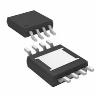
LT3085MPMS8E#TRPBF Linear Technology, LT3085MPMS8E#TRPBF Datasheet - Page 10

LT3085MPMS8E#TRPBF
Manufacturer Part Number
LT3085MPMS8E#TRPBF
Description
IC LDO REG ADJ 500MA 8-MSOP
Manufacturer
Linear Technology
Datasheet
1.LT3085EDCBTRMPBF.pdf
(28 pages)
Specifications of LT3085MPMS8E#TRPBF
Regulator Topology
Positive Adjustable
Voltage - Output
Adjustable
Voltage - Input
1.2 ~ 36 V
Voltage - Dropout (typical)
1.35V @ 500mA
Number Of Regulators
1
Current - Output
500mA
Current - Limit (min)
500mA
Operating Temperature
-55°C ~ 125°C
Mounting Type
Surface Mount
Package / Case
8-MSOP Exposed Pad, 8-HMSOP, 8-eMSOP
Lead Free Status / RoHS Status
Lead free / RoHS Compliant
Available stocks
Company
Part Number
Manufacturer
Quantity
Price
LT3085
APPLICATIONS INFORMATION
Input Capacitance and Stability
The LT3085 is designed to be stable with a minimum
capacitance of 1μF at each input pin. Ceramic capacitors
with low ESR are available for use to bypass these pins,
but in cases where long wires connect the LT3085 inputs
to a power supply (and also from ground of the LT3085
circuitry back to power supply ground), this causes insta-
bilities. This happens due to the wire inductance forming
an LC tank circuit with the input capacitor and not as a
result of instability on the LT3085.
The self-inductance, or isolated inductance, of a wire is
directly proportional to its length. The diameter does not
have a major infl uence on its self-inductance. As an ex-
ample, the self-inductance of a 2-AWG isolated wire with a
diameter of 0.26in. is approximately half the self-inductance
of a 30-AWG wire with a diameter of 0.01in. One foot of
30-AWG wire has 465nH of self-inductance.
The overall self-inductance of a wire is reduced in one of
two ways. One is to divide the current fl owing towards
the LT3085 between two parallel conductors. In this
case, the farther apart the wires are from each other, the
more the self-inductance is reduced, up to a 50% reduc-
tion when placed a few inches apart. Splitting the wires
basically connects two equal inductors in parallel, but
placing them in close proximity gives the wires mutual
inductance adding to the self-inductance. The second
and most effective way to reduce overall inductance is to
place both forward- and return-current conductors (the
wire for the input and the wire for ground) in very close
proximity. Two 30-AWG wires separated by only 0.02in.
used as forward- and return-current conductors reduce
the overall self-inductance to approximately one-fi fth that
of a single isolated wire.
If the LT3085 is powered by a battery mounted in close
proximity on the same circuit board, a 2.2μF input capaci-
tor is suffi cient for stability. When powering from distant
supplies, use a larger input capacitor based on a guide-
line of 1μF plus another 1μF per 8 inches of wire length.
10
As power supply impedance does vary, the amount of
capacitance needed to stabilize your application will also
vary. Extra capacitance placed directly on the output of
the power supply requires an order of magnitude more
capacitance as opposed to placing extra capacitance close
to the LT3085.
Using series resistance between the power supply and
the input of the LT3085 also stabilizes the application.
As little as 0.1Ω to 0.5Ω, often less, is all that is needed
to provide damping in the circuit. If the extra impedance
between the power supply and the input is unacceptable,
placing the resistors in series with the capacitors will pro-
vide damping to prevent the LC resonance from causing
full-blown oscillation.
Stability and Output Capacitance
The LT3085 requires an output capacitor for stability. It
is designed to be stable with most low ESR capacitors
(typically ceramic, tantalum or low ESR electrolytic). A
minimum output capacitor of 2.2μF with an ESR of 0.5Ω
or less is recommended to prevent oscillations. Larger
values of output capacitance decrease peak deviations
and provide improved transient response for larger load
current changes. Bypass capacitors, used to decouple
individual components powered by the LT3085, increase
the effective output capacitor value.
For improvement in transient performance, place a capaci-
tor across the voltage setting resistor. Capacitors up to
1μF can be used. This bypass capacitor reduces system
noise as well, but start-up time is proportional to the time
constant of the voltage setting resistor (R
and SET pin bypass capacitor.
Extra consideration must be given to the use of ceramic
capacitors. Ceramic capacitors are manufactured with a
variety of dielectrics, each with different behavior across
temperature and applied voltage. The most common
dielectrics used are specifi ed with EIA temperature
characteristic codes of Z5U, Y5V, X5R and X7R. The Z5U and
Y5V dielectrics are good for providing high capacitances
SET
in Figure 1)
3085fb


