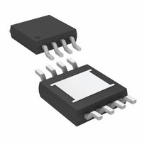
LT3085MPMS8E#TRPBF Linear Technology, LT3085MPMS8E#TRPBF Datasheet - Page 11

LT3085MPMS8E#TRPBF
Manufacturer Part Number
LT3085MPMS8E#TRPBF
Description
IC LDO REG ADJ 500MA 8-MSOP
Manufacturer
Linear Technology
Datasheet
1.LT3085EDCBTRMPBF.pdf
(28 pages)
Specifications of LT3085MPMS8E#TRPBF
Regulator Topology
Positive Adjustable
Voltage - Output
Adjustable
Voltage - Input
1.2 ~ 36 V
Voltage - Dropout (typical)
1.35V @ 500mA
Number Of Regulators
1
Current - Output
500mA
Current - Limit (min)
500mA
Operating Temperature
-55°C ~ 125°C
Mounting Type
Surface Mount
Package / Case
8-MSOP Exposed Pad, 8-HMSOP, 8-eMSOP
Lead Free Status / RoHS Status
Lead free / RoHS Compliant
Available stocks
Company
Part Number
Manufacturer
Quantity
Price
APPLICATIONS INFORMATION
in a small package, but they tend to have strong voltage
and temperature coeffi cients as shown in Figures 2
and 3. When used with a 5V regulator, a 16V 10μF Y5V
capacitor can exhibit an effective value as low as 1μF to
2μF for the DC bias voltage applied and over the operating
temperature range. The X5R and X7R dielectrics result in
more stable characteristics and are more suitable for use
as the output capacitor. The X7R type has better stability
across temperature, while the X5R is less expensive and is
available in higher values. Care still must be exercised when
using X5R and X7R capacitors; the X5R and X7R codes
only specify operating temperature range and maximum
capacitance change over temperature. Capacitance change
due to DC bias with X5R and X7R capacitors is better than
Y5V and Z5U capacitors, but can still be signifi cant enough
to drop capacitor values below appropriate levels. Capacitor
DC bias characteristics tend to improve as component
case size increases, but expected capacitance at operating
voltage should be verifi ed.
Voltage and temperature coeffi cients are not the only
sources of problems. Some ceramic capacitors have a
Figure 2. Ceramic Capacitor DC Bias Characteristics
–100
–20
–40
–60
–80
20
0
0
2
4
DC BIAS VOLTAGE (V)
BOTH CAPACITORS ARE 16V,
1210 CASE SIZE, 10μF
6
8
Y5V
X5R
10
12
14
3085 F02
16
piezoelectric response. A piezoelectric device generates
voltage across its terminals due to mechanical stress,
ceramic capacitor the stress can be induced by vibrations
in the system or thermal transients.
Paralleling Devices
LT3085’s may be paralleled with other LT308X devices to
obtain higher output current. The SET pins are tied together
and the IN pins are tied together. This is the same whether
it’s in three terminal mode or has separate input supplies.
The outputs are connected in common using a small piece
of PC trace as a ballast resistor to equalize the currents.
PC trace resistance in milliohms/inch is shown in Table
1. Only a tiny area is needed for ballasting.
Table 1. PC Board Trace Resistance
Trace resistance is measured in mΩ/in
Figure 3. Ceramic Capacitor Temperature Characteristics
WEIGHT (oz)
1
2
–100
–20
–40
–60
–80
40
20
0
–50
BOTH CAPACITORS ARE 16V,
1210 CASE SIZE, 10μF
–25
10 mil WIDTH
0
TEMPERATURE (°C)
54.3
27.1
25
50
Y5V
75
X5R
100
3085 F03
20 mil WIDTH
LT3085
125
27.1
13.6
11
3085fb


