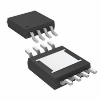
LT3085MPMS8E#TRPBF Linear Technology, LT3085MPMS8E#TRPBF Datasheet - Page 14

LT3085MPMS8E#TRPBF
Manufacturer Part Number
LT3085MPMS8E#TRPBF
Description
IC LDO REG ADJ 500MA 8-MSOP
Manufacturer
Linear Technology
Datasheet
1.LT3085EDCBTRMPBF.pdf
(28 pages)
Specifications of LT3085MPMS8E#TRPBF
Regulator Topology
Positive Adjustable
Voltage - Output
Adjustable
Voltage - Input
1.2 ~ 36 V
Voltage - Dropout (typical)
1.35V @ 500mA
Number Of Regulators
1
Current - Output
500mA
Current - Limit (min)
500mA
Operating Temperature
-55°C ~ 125°C
Mounting Type
Surface Mount
Package / Case
8-MSOP Exposed Pad, 8-HMSOP, 8-eMSOP
Lead Free Status / RoHS Status
Lead free / RoHS Compliant
Available stocks
Company
Part Number
Manufacturer
Quantity
Price
LT3085
APPLICATIONS INFORMATION
The problem occurs with a heavy output load when the
input voltage is high and the output voltage is low. Com-
mon situations are immediately after the removal of a
short circuit. The load line for such a load may intersect
the output current curve at two points. If this happens,
there are two stable operating points for the regulator.
With this double intersection, the input power supply may
need to be cycled down to zero and brought up again to
make the output recover.
Load Regulation
Because the LT3085 is a fl oating device (there is no ground
pin on the part, all quiescent and drive current is delivered
to the load), it is not possible to provide true remote load
sensing. Load regulation will be limited by the resistance
of the connections between the regulator and the load.
The data sheet specifi cation for load regulation is Kelvin
sensed at the pins of the package. Negative side sensing
is a true Kelvin connection, with the bottom of the voltage
setting resistor returned to the negative side of the load
(see Figure 7). Connected as shown, system load regulation
will be the sum of the LT3085 load regulation and the
parasitic line resistance multiplied by the output current.
It is important to keep the positive connection between
the regulator and load as short as possible and use large
wire or PC board traces.
Internal Parasitic Diodes and Protection Diodes
In normal operation, the LT3085 does not require protection
diodes. Older three-terminal regulators require protection
diodes between the VOUT pin and the input pin or between
the ADJ pin and the VOUT pin to prevent die overstress.
14
Figure 7. Connections for Best Load Regulation
V
CONTROL
IN
SET R
LT3085
+
–
SET
OUT
RESISTANCE
PARASITIC
R
R
R
P
P
P
3085 F07
LOAD
On the LT3085, internal resistors and diodes limit current
paths on the SET pin. Even with bypass capacitors on the
SET pin, no protection diode is needed to ensure device
safety under short-circuit conditions. The SET pin handles
±10V (either transient or DC) with respect to OUT without
any device degradation.
Internal parasitic diodes exist between OUT and the two
inputs. Negative input voltages are transferred to the output
and may damage sensitive loads. Reverse-biasing either
input to OUT will turn on these parasitic diodes and allow
current fl ow. This current fl ow will bias internal nodes
of the LT3085 to levels that possibly cause errors when
suddenly returning to normal operating conditions and
expecting the device to start and operate. Prediction of
results of a bias fault is impossible, immediate return to
normal operating conditions can be just as diffi cult after
a bias fault. Suffi ce it to say that extra wait time, power
cycling, or protection diodes may be needed to allow the
LT3085 to return to a normal operating mode as quickly
as possible.
Protection diodes are not otherwise needed between
the OUT pin and IN pin. The internal diodes can handle
microsecond surge currents of up to 50A. Even with
large output capacitors, obtaining surge currents of those
magnitudes is diffi cult in normal operation. Only with large
output capacitors, such as 1000μF to 5000μF , and with
IN instantaneously shorted to ground will damage occur.
A crowbar circuit at IN is capable of generating those
levels of currents, and then protection diodes from OUT
to IN are recommended. Normal power supply cycling or
system “hot plugging and unplugging” does not do any
damage.
A protection diode between OUT and V
not needed. The internal parasitic diode on V
the LT3085 handles microsecond surge currents of 1A to
10A. Again, this only occurs when using crowbar circuits
with large value output capacitors. Since the V
pin is usually a low current supply, this is unlikely. Still,
a protection diode is recommended if V
instantaneously shorted to ground. Normal power supply
cycling or system “hot plugging and unplugging” does
not do any damage.
CONTROL
CONTROL
CONTROL
is usually
CONTROL
can be
3085fb
of


