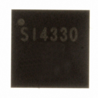
SI4330-B1-FM Silicon Laboratories Inc, SI4330-B1-FM Datasheet - Page 51

SI4330-B1-FM
Manufacturer Part Number
SI4330-B1-FM
Description
IC RCVR ISM 960MHZ 3.6V 20-QFN
Manufacturer
Silicon Laboratories Inc
Type
ISM Receiverr
Specifications of SI4330-B1-FM
Package / Case
20-QFN
Frequency
960MHz
Sensitivity
-118dBm
Data Rate - Maximum
128kbps
Modulation Or Protocol
FSK, GFSK, OOK
Current - Receiving
18.5mA
Data Interface
PCB, Surface Mount
Antenna Connector
PCB, Surface Mount
Voltage - Supply
1.8 V ~ 3.6 V
Operating Temperature
-40°C ~ 85°C
Operating Frequency
240 MHz to 960 MHz
Operating Supply Voltage
3 V
Maximum Operating Temperature
+ 85 C
Minimum Operating Temperature
- 40 C
Mounting Style
SMD/SMT
Supply Current
18.5 mA
Package
20QFN EP
Maximum Data Rate
256 Kbps
Transmission Media Type
Wireless
Power Supply Type
Analog
Typical Operating Supply Voltage
3 V
Minimum Operating Supply Voltage
1.8 V
Maximum Operating Supply Voltage
3.6 V
Lead Free Status / RoHS Status
Lead free / RoHS Compliant
Features
-
Applications
-
Memory Size
-
Lead Free Status / Rohs Status
Lead free / RoHS Compliant
Other names
336-1629-5
SI4330-V2-FM
SI4330-V2-FM
Available stocks
Company
Part Number
Manufacturer
Quantity
Price
Part Number:
SI4330-B1-FM
Manufacturer:
SILICON LABS/芯科
Quantity:
20 000
Company:
Part Number:
SI4330-B1-FM-02T
Manufacturer:
SILICON
Quantity:
112
Company:
Part Number:
SI4330-B1-FMR
Manufacturer:
HIROSE
Quantity:
3 200
Part Number:
SI4330-B1-FMR
Manufacturer:
SILICON LABS/芯科
Quantity:
20 000
8.10. RSSI and Clear Channel Assessment
Received signal strength indicator (RSSI) is an estimate of the signal strength in the channel to which the receiver
is tuned. The RSSI value can be read from an 8-bit register with 0.5 dB resolution per bit. Figure 23 demonstrates
the relationship between input power level and RSSI value.The absolute value of the RSSI will change slightly
depending on the modem settings. The RSSI may be read at anytime, but an incorrect error may rarely occur. The
RSSI value may be incorrect if read during the update period. The update period is approximately 10 ns every
4 Tb. For 10 kbps, this would result in a 1 in 40,000 probability that the RSSI may be read incorrectly. This
probability is extremely low, but to avoid this, one of the following options is recommended: majority polling,
reading the RSSI value within 1 Tb of the RSSI interrupt, or using the RSSI threshold described in the next
paragraph for Clear Channel Assessment (CCA).
For CCA, threshold is programmed into rssith[7:0] in "Register 27h. RSSI Threshold for Clear Channel Indicator."
After the RSSI is evaluated in the preamble, a decision is made if the signal strength on this channel is above or
below the threshold. If the signal strength is above the programmed threshold then the RSSI status bit, irssi, in
"Register 04h. Interrupt/Status 2" will be set to 1. The RSSI status can also be routed to a GPIO line by configuring
the GPIO configuration register to GPIOx[3:0] = 1110.
Add R/W
26
27
R/W
R
250
200
150
100
50
RSSI Threshold for Clear Channel Indicator
0
-120
Received Signal Strength Indicator
Function/Description
-100
Figure 23. RSSI Value vs. Input Power
-80
rssith[7]
RSSI vs Input Power
rssi[7]
D7
-60
rssith[6]
rssi[6]
Rev 1.0
In Pow [dBm]
D6
rssith[5]
rssi[5]
D5
-40
rssith[4]
rssi[4]
D4
rssith[3]
rssi[3]
D3
-20
rssith[2]
rssi[2]
D2
rssith[1]
rssi[1]
0
Si4330-B1
D1
rssith[0]
rssi[0]
D0
20
POR Def.
00h
—
51


