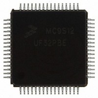
MC9S08JE64CLH Freescale Semiconductor, MC9S08JE64CLH Datasheet - Page 14

MC9S08JE64CLH
Manufacturer Part Number
MC9S08JE64CLH
Description
IC MCU 8BIT 64K FLASH 64LQFP
Manufacturer
Freescale Semiconductor
Series
HCS08r
Datasheet
1.MC9S08JE128CMB.pdf
(44 pages)
Specifications of MC9S08JE64CLH
Core Processor
HCS08
Core Size
8-Bit
Speed
48MHz
Connectivity
I²C, SCI, SPI, USB
Peripherals
LVD, POR, PWM, WDT
Number Of I /o
33
Program Memory Size
64KB (64K x 8)
Program Memory Type
FLASH
Ram Size
12K x 8
Voltage - Supply (vcc/vdd)
1.8 V ~ 3.6 V
Data Converters
A/D 6x12b
Oscillator Type
Internal
Operating Temperature
-40°C ~ 85°C
Package / Case
64-LQFP
Processor Series
S08JE
Core
HCS08
Data Bus Width
8 bit
Data Ram Size
12 KB
Maximum Clock Frequency
48 MHz
Operating Supply Voltage
- 0.3 V to + 3.8 V
Maximum Operating Temperature
+ 105 C
3rd Party Development Tools
EWS08
Development Tools By Supplier
TWR-SER, TWR-ELEV, TWR-MCF51JE-KIT, TWR-S08JE128-KIT, TWR-LCD
Minimum Operating Temperature
- 40 C
On-chip Adc
12 bit
Lead Free Status / RoHS Status
Lead free / RoHS Compliant
Eeprom Size
-
Lead Free Status / Rohs Status
Details
Available stocks
Company
Part Number
Manufacturer
Quantity
Price
Company:
Part Number:
MC9S08JE64CLH
Manufacturer:
Freescale Semiconductor
Quantity:
10 000
Preliminary Electrical Characteristics
2.3
This section provides information about operating temperature range, power dissipation, and package thermal resistance. Power
dissipation on I/O pins is usually small compared to the power dissipation in on-chip logic and it is user-determined rather than
being controlled by the MCU design. In order to take P
actual pin voltage and V
(heavy loads), the difference between pin voltage and V
The average chip-junction temperature (T
where:
For most applications, P
is:
14
1
2
3
4
T
θ
P
P
P
Junction temperature is a function of die size, on-chip power dissipation, package thermal resistance, mounting
site (board) temperature, ambient temperature, air flow, power dissipation of other components on the board, and
board thermal resistance.
Junction to Ambient Natural Convection
1s — Single layer board, one signal layer
2s2p — Four layer board, 2 signal and 2 power layers
A
JA
D
int
I/O
Thermal Characteristics
#
1
2
3
4
= Ambient temperature, °C
= P
= Package thermal resistance, junction-to-ambient, °C/W
= I
= Power dissipation on input and output pins — user determined
int
DD
+ P
× V
Symbol
T
SS
I/O
I/O
JMAX
θ
θ
T
DD
JA
JA
or V
A
<< P
, Watts — chip internal power
DD
int
and multiply by the pin current for each I/O pin. Except in cases of unusually high pin current
and can be neglected. An approximate relationship between P
Operating temperature range (packaged):
Maximum junction temperature
Thermal resistance
Thermal resistance
J
) in °C can be obtained from:
Table 6. Thermal Characteristics
Preliminary — Subject to Change
P
T
D
J
= K ÷ (T
= T
I/O
A
1,2,3,4
1, 2, 3, 4
SS
+ (P
into account in power calculations, determine the difference between
Rating
or V
J
MC9S08JE128
MC9S08JE64
81-pin MBGA
80-pin LQFP
64-pin LQFP
81-pin MBGA
80-pin LQFP
64-pin LQFP
+ 273°C)
D
Single-layer board — 1s
Four-layer board — 2s2p
DD
× θ
will be very small.
JA
)
–40 to 105
–40 to 105
Value
D
135
77
55
68
47
40
49
and T
Freescale Semiconductor
J
(if P
I/O
°C/W
°C/W
Unit
°C
°C
is neglected)
Eqn. 1
Eqn. 2


