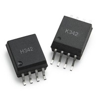
ACPL-K342-060E Avago Technologies US Inc., ACPL-K342-060E Datasheet - Page 14

ACPL-K342-060E
Manufacturer Part Number
ACPL-K342-060E
Description
Logic Output Optocouplers Optocoupler
Manufacturer
Avago Technologies US Inc.
Series
-r
Type
Gate Driver, Miller Clampr
Datasheet
1.ACPL-K342-000E.pdf
(19 pages)
Specifications of ACPL-K342-060E
Fall Time
18 ns
Rise Time
22 ns
Maximum Propagation Delay Time
0.35 us
Maximum Forward Diode Voltage
1.95 V
Minimum Forward Diode Voltage
1.2 V
Maximum Reverse Diode Voltage
5 V
Maximum Continuous Output Current
2.5 A
Maximum Power Dissipation
255 mW
Maximum Operating Temperature
+ 105 C
Minimum Operating Temperature
- 40 C
Package / Case
SOIC-8
No. Of Channels
1
Isolation Voltage
5kV
Optocoupler Output Type
Gate Drive
Input Current
230mA
Output Voltage
30V
Opto Case Style
SOIC
No. Of Pins
8
Peak Reflow Compatible (260 C)
Yes
Rohs Compliant
Yes
Voltage - Isolation
5000Vrms
Input Type
DC
Voltage - Supply
15 V ~ 30 V
Operating Temperature
-40°C ~ 105°C
Mounting Type
Surface Mount
Leaded Process Compatible
Yes
Lead Free Status / RoHS Status
Lead free / RoHS Compliant
Figure 31. t
Figure 32. CMR test circuit with split resistors network and waveforms.
Application Information
Product Overview Description
The ACPL-H342/K342 is an optically isolated power output
stage capable of driving IGBTs of up to 150 A and 1200
V. It has very high CMR rating which allows the micro-
controller and the IGBT to operate at very large common
mode noise found in industrial motor drives and other
power switching applications. And to achieve better
system reliability in such noisy environment, this power
control device incorporates new features like Active Miller
clamp, Rail-to-Rail output voltage, Anti-cross conduction
and LED input current hysteresis.
Active Miller clamp function eliminates the need of
negative gate drive in most application and allows the
use of simple bootstrap supply for high side driver. Rail-to-
Rail output voltage ensures that the IGBT’s gate voltage is
driven to the optimum intended level with no power loss
across IGBT. Anti-cross conduction prevents current shoot
through between the high and low side of half bridge
IGBT configuration. This will help to simplify the controller
design in terms of having to account for the delay needed
at the LED input. And lastly, the LED input current hyster-
esis prevents output oscillation if insufficient LED driving
current is applied. This will eliminates the need of addi-
tional Schmitt trigger circuit at the input LED.
This feature rich IGBT gate driver is designed to increase the
performance and reliability of a motor drive without the
cost, size, and complexity of external circuitry or control.
14
20kHz, 50% Duty
5 V
I
F
= 7 to 16mA,
Cycle
+ _
+ _
PLH
170 ohm
, t
PHL
, t
r
and t
170 ohm
f
1
2
3
4
test circuit and waveforms.
1
2
3
4
V
CM
= 1500V
9
V
&/$03
CLAMP
9
V
&/$03
CLAMP
8
7
6
5
1μF
8
7
6
5
1μF
Recommended Application Circuit
The recommended application circuit shown in Figure 33
illustrates a typical gate drive implementation using the
ACPL-H342. The following describes about driving IGBT.
However, it is also applicable to MOSFET. Designers will
need to adjust the V
MOSFET or IGBT gate threshold requirements (Recom-
mended V
The supply bypass capacitors (1 μF) provide the large
transient currents necessary during a switching transition.
Because of the transient nature of the charging currents,
a low current (2.5mA) power supply will be enough to
power the device. The split resistors across the LED will
provide a high CMR response by providing a balanced re-
sistance network across the LED.
The gate resistor R
and controls the IGBT collector voltage rise and fall times.
In PC board design, care should be taken to avoid routing
the IGBT collector or emitter traces close to the ACPL-H342
input as this can result in unwanted coupling of transient
signals into ACPL-H342 and degrade performance.
10Ω
25nF
V
V
O
O
+ _
+ _
V
+ _
+ _
CC
CC
V
= 30V
CC
= 18V for IGBT and 12V for MOSFET).
= 15 to 30V
G
CC
serves to limit gate charge current
supply voltage, depending on the
10 mA
P$


