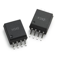
ACPL-K342-060E Avago Technologies US Inc., ACPL-K342-060E Datasheet - Page 18

ACPL-K342-060E
Manufacturer Part Number
ACPL-K342-060E
Description
Logic Output Optocouplers Optocoupler
Manufacturer
Avago Technologies US Inc.
Series
-r
Type
Gate Driver, Miller Clampr
Datasheet
1.ACPL-K342-000E.pdf
(19 pages)
Specifications of ACPL-K342-060E
Fall Time
18 ns
Rise Time
22 ns
Maximum Propagation Delay Time
0.35 us
Maximum Forward Diode Voltage
1.95 V
Minimum Forward Diode Voltage
1.2 V
Maximum Reverse Diode Voltage
5 V
Maximum Continuous Output Current
2.5 A
Maximum Power Dissipation
255 mW
Maximum Operating Temperature
+ 105 C
Minimum Operating Temperature
- 40 C
Package / Case
SOIC-8
No. Of Channels
1
Isolation Voltage
5kV
Optocoupler Output Type
Gate Drive
Input Current
230mA
Output Voltage
30V
Opto Case Style
SOIC
No. Of Pins
8
Peak Reflow Compatible (260 C)
Yes
Rohs Compliant
Yes
Voltage - Isolation
5000Vrms
Input Type
DC
Voltage - Supply
15 V ~ 30 V
Operating Temperature
-40°C ~ 105°C
Mounting Type
Surface Mount
Leaded Process Compatible
Yes
Lead Free Status / RoHS Status
Lead free / RoHS Compliant
The ACPL-H342 with the Anti-Cross feature has a PDD
of -10ns and a PDD
a negative value, the t
Thus this simplified the design without having to add any
amount of delay for the input LEDs as shown in Figure 39.
Figure 39. Anti-Cross to prevent shoot through
Figure 40. Determining maximum dead time
18
Symbol
t
t
PDD (t
PLH
PHL
I
V
V
I
I
V
V
I
LED1
LED2
LED1
LED2
OUT1
OUT2
OUT1
OUT2
PHL
Q2 OFF
Q2 OFF
- t
PLH
)
Q1 ON
t
t
t
PHLMIN
PLHMAX
PLHMIN
t
MAX
PLHMIN
t
PLHMAX
PHLMAX
Q1 ON
t
Min.
0.100
0.050
-0.010
of -200ns. Since the PDD is always
PHLMAX
PDD
= Minimum Dead Time
is always faster than t
MAX
Typ.
0.260
0.145
-0.100
= -200 ns
PDD
= Minimum Dead Time
MIN
Max.
0.350
0.250
-0.200
= -10 ns
Units
Ps
Ps
Ps
PLHMIN
Q1 OFF
Q2 ON
Q1 OFF
Q2 ON
MIN
.
Dead time is the time period during which both the
high(Q1) and low(Q2) side transistor are off. During this
time, no work is done and this reduces the efficiency of
the inverter or motor drive. The minimum and maximum
dead time is shown in Figure 39 and 40 and is equivalent
to the PDD
skewed propagation delay configuration, ACPL-H342
shows a smaller maximum dead time as compared to its
predecessor, HCPL-3120 as shown in figure 41 and hence
an improve in efficiency. Note that the propagation delays
used to calculate PDD and dead time are taken at equal
temperature and test conditions since the optocou-
plers under consideration are typically mounted in close
proximity to each other and are switching identical IGBTs.
Figure 41. HCPL-3120 maximum dead time
I
V
V
I
LED1
LED2
OUT1
OUT2
MIN
and PDD
Q1 ON
t
t
Q2 OFF
PHLMIN
PHLMAX
MAX
Maximum Dead Time
= (t
= (t
= PDD
= 350 (-350) = 700 ns
t
. Due to the smaller PDD and
PLHMIN
PHLMAX
PHLMAX
MAX
t
PLHMAX
PDD
t
t
Q1 OFF
PHLMIN
PLHMIN
MIN
) + (t
) + (t
Q2 ON
PLHMAX
PHLMIN
t
t
PLHMAX
PLHMIN
)
)


