MC56F8245VLD Freescale Semiconductor, MC56F8245VLD Datasheet - Page 85
MC56F8245VLD
Manufacturer Part Number
MC56F8245VLD
Description
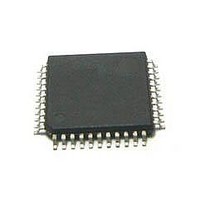
DSC 48K FLASH 60MHZ 44-LQFP
Manufacturer
Freescale Semiconductor
Series
56F8xxxr
Datasheets
1.TWR-56F8257.pdf
(88 pages)
2.MC56F8245VLD.pdf
(14 pages)
3.MC56F8245VLD.pdf
(2 pages)
4.MC56F8245VLD.pdf
(629 pages)
Specifications of MC56F8245VLD
Core Processor
56800E
Core Size
16-Bit
Speed
60MHz
Connectivity
CAN, I²C, LIN, SCI, SPI
Peripherals
LVD, POR, PWM, WDT
Number Of I /o
35
Program Memory Size
48KB (24K x 16)
Program Memory Type
FLASH
Ram Size
3K x 16
Voltage - Supply (vcc/vdd)
3 V ~ 3.6 V
Data Converters
A/D 8x12b, D/A 1x12b
Oscillator Type
Internal
Operating Temperature
-40°C ~ 105°C
Package / Case
44-LQFP
Product
DSCs
Processor Series
56800E
Core
56800E
Device Million Instructions Per Second
60 MIPs
Maximum Clock Frequency
60 MHz
Number Of Programmable I/os
35
Data Ram Size
6 KB
Operating Supply Voltage
3.3 V
Maximum Operating Temperature
+ 105 C
Mounting Style
SMD/SMT
Minimum Operating Temperature
- 40 C
On-chip Adc
12 bit, 4 Channel
Package
44LQFP
Family Name
MC56F82xx
Maximum Speed
60 MHz
Data Bus Width
16 Bit
Interface Type
I2C/SCI/SPI
On-chip Dac
1-chx12-bit
Number Of Timers
8
Lead Free Status / RoHS Status
Lead free / RoHS Compliant
Eeprom Size
-
Lead Free Status / Rohs Status
Details
Available stocks
Company
Part Number
Manufacturer
Quantity
Price
Company:

Part Number:
MC56F8245VLD
Manufacturer:
FREESCAL
Quantity:
269
Company:
Part Number:
MC56F8245VLD
Manufacturer:
Freescale Semiconductor
Quantity:
10 000


Appendix A
Interrupt Vector Table
Table 48
is organized with higher-priority vectors at the top and lower-priority interrupts lower in the table. As indicated, the priority of
an interrupt can be assigned to different levels, allowing some control over interrupt priorities. All level 3 interrupts are serviced
before level 2 and so on. For a selected priority level, the lowest vector number has the highest priority.
The location of the vector table is determined by the vector base address (VBA). See the device’s reference manual for details.
By default, the chip reset address and COP reset address correspond to vector 0 and 1 of the interrupt vector table. In these cases,
the first two locations in the vector table must contain branch or JMP instructions. All other entries must contain JSR
instructions.
Freescale Semiconductor
Peripheral
ADCB_CC
ADCA_CC
ADC_Err
provides the MC56F825x/MC56F824x’s reset and interrupt priority structure, including on-chip peripherals. The table
TMRB3
TMRB2
TMRB1
TMRB0
OCCS
Core
Core
Core
Core
Core
Core
Core
Core
Core
Core
Core
Core
Core
Core
CAN
CAN
PS
Number
Vector
10
11
12
13
14
15
16
17
18
19
20
21
22
23
24
2
3
4
5
6
7
8
9
MC56F825x/MC56F824x Digital Signal Controller, Rev. 3
Priority
Level
1 - 3
1 - 3
1 - 3
1 - 3
1 - 3
1 - 3
1 - 3
0 - 2
0 - 2
0 - 2
0 - 2
0 - 2
0 - 2
0 - 2
0 - 2
0 - 2
3
3
3
3
2
1
0
Table 48. Interrupt Vector Table Contents
Vector Base
Address +
P:0x0C
P:0x1C
P:0x2C
P:0x00
P:0x02
P:0x04
P:0x06
P:0x08
P:0x0A
P:0x0E
P:0x10
P:0x12
P:0x14
P:0x1A
P:0x1E
P:0x20
P:0x22
P:0x24
P:0x26
P:0x28
P:0x2A
P:0x2E
P:0x30
P:0x16
P:0x18
Phase-Locked Loop Loss of Locks and Loss of Clock
ADC Zero crossing, Low limit, and high limit interrupt
ADCB Conversion Complete Interrupt
ADCA Conversion Complete Interrupt
Quad Timer B, Channel 3 Interrupt
Quad Timer B, Channel 0 Interrupt
Quad Timer B, Channel 2Interrupt
Quad Timer B, Channel 1Interrupt
Reserved for COP Reset Overlay
EOnCE Transmit Register Empty
Misaligned Long Word Access
EOnCE Receive Register Full
Reserved for Reset Overlay
EOnCE Breakpoint Unit
CAN Transmit Interrupt
CAN Receive Interrupt
EOnCE Step Counter
Low-Voltage Interrupt
EOnCE Trace Buffer
Interrupt Function
HW Stack Overflow
Illegal Instruction
SW Interrupt 3
SW Interrupt 2
SW Interrupt 1
SW Interrupt 0
1
Interrupt Vector Table
2
85
Related parts for MC56F8245VLD
Image
Part Number
Description
Manufacturer
Datasheet
Request
R

Part Number:
Description:
Manufacturer:
Freescale Semiconductor, Inc
Datasheet:
Part Number:
Description:
Manufacturer:
Freescale Semiconductor, Inc
Datasheet:
Part Number:
Description:
Manufacturer:
Freescale Semiconductor, Inc
Datasheet:
Part Number:
Description:
Manufacturer:
Freescale Semiconductor, Inc
Datasheet:
Part Number:
Description:
Manufacturer:
Freescale Semiconductor, Inc
Datasheet:
Part Number:
Description:
Manufacturer:
Freescale Semiconductor, Inc
Datasheet:
Part Number:
Description:
Manufacturer:
Freescale Semiconductor, Inc
Datasheet:
Part Number:
Description:
Manufacturer:
Freescale Semiconductor, Inc
Datasheet:
Part Number:
Description:
Manufacturer:
Freescale Semiconductor, Inc
Datasheet:
Part Number:
Description:
Manufacturer:
Freescale Semiconductor, Inc
Datasheet:
Part Number:
Description:
Manufacturer:
Freescale Semiconductor, Inc
Datasheet:
Part Number:
Description:
Manufacturer:
Freescale Semiconductor, Inc
Datasheet:
Part Number:
Description:
Manufacturer:
Freescale Semiconductor, Inc
Datasheet:
Part Number:
Description:
Manufacturer:
Freescale Semiconductor, Inc
Datasheet:
Part Number:
Description:
Manufacturer:
Freescale Semiconductor, Inc
Datasheet: