CS82C5296 Intersil, CS82C5296 Datasheet - Page 14
CS82C5296
Manufacturer Part Number
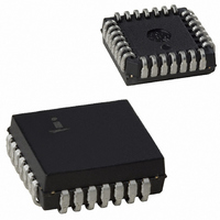
CS82C5296
Description
IC UART/BRG 5V 16MHZ 28-PLCC
Manufacturer
Intersil
Datasheet
1.IS82C52Z.pdf
(20 pages)
Specifications of CS82C5296
Features
Single Chip UART/BRG
Number Of Channels
1, UART
Protocol
RS232C
Voltage - Supply
4.5 V ~ 5.5 V
With Parallel Port
Yes
With False Start Bit Detection
Yes
With Modem Control
Yes
With Cmos
Yes
Mounting Type
Surface Mount
Package / Case
28-LCC (J-Lead)
Lead Free Status / RoHS Status
Contains lead / RoHS non-compliant
Fifo's
-
With Auto Flow Control
-
With Irda Encoder/decoder
-
Available stocks
Company
Part Number
Manufacturer
Quantity
Price


UART Timing Characterization
All parameters listed in this table were laboratory bench characterized at room temperature on a small sample of parts. No guarantee is implied. The main intent here is
to clarify functional operation of the 82C52.
82C52 UART Timing
NOTES:
1. Prescaler rate of divide by 1, Divisor Select rate of “external” (divide by 1). The Baud Rate Clock (CO-BRG) operates at 16 times the user
2. A. With TR (Transmitter Register) initially empty, TDTX occurs from the 5th falling edge of CO(BRG) after WR goes high.
3. TBRE bit D6 in USR is updated each time TBRE changes state.
4. A. With TR initially empty, TCLTH(TBRE) occurs from the 4th falling edge of CO(BRG) after WR goes high.
5. A. INT on TC: INTEN enabled; USR bit D5(TC) is updated at this time regardless of interrupt configuration.
6. TCTHX is time before end of last Stop bit by which CTS must be inactive (high) to prevent transmission of the character waiting in TBR.
7. DR bit D7 in USR is updated each time DR changes state. TDRH always from trailing edge of 11th CO(BRG) in last Stop bit.
(15)
(16)
(17)
(18)
(19)
(20)
(21)
(22)
(23)
(24)
(25)
(26)
(27)
programmed bit rate. For example, at 1200 baud: TCY = 1/(16 x 1200) = 52.1µs.
B. With TR initially full, TDTX occurs from the trailing edge of the 16th CO(BRG) in the last Stop bit provided WR went high by the trailing edge
C. With CTS high (disable transmit) and TBR full, TDTX occurs from the 5th falling edge of CO(BRG) after CTS goes low.
B. With TR initially full, TCLTH(TBRE) occurs from the trailing edge of the 15th CO(BRG) in the last Stop bit provided WR went high by the
C. With CTS high (disable transmit) and TBR full, TCLTH(TBRE) occurs from the 4th falling edge of CO(BRG) after CTS goes low.
B. INTR on receive flags OE, FE, PE, and RBRK: INTEN enabled; Respective USR bits updated at this time regardless of interrupt configura-
C. INTR on MS: INTEN and MIEN enabled; USR bit D4(MS) is updated at this time regardless of INTEN/MIEN.
SYMBOL
of the 12th CO(BRG) in the last Stop bit.
trailing edge of the 12th CO(BRG) in the last Stop bit.
- INT on TC occurs from the trailing edge of the 11th CO(BRG) in the last Stop bit if TBR empty at that time.
tion.
- INT on OE, FE, PE, RBRK occurs from the trailing edge of the 11th CO(BRG) in the last Stop bit. To avoid OE, RD(RBR) must go low by
- INTR on MS occurs whenever CTS or DSR input changes state.
TCTHX
TWLTL
TCLTH
TRLDL
TWHO
TRLIL
TDRH
the trailing edge of the 8th CO(BRG) in the last Stop bit.
TDTX
TIHM
TIHF
TCY
TS1
TS2
CO(IX) Delay from IX
CO (BRG) Delay from IX
CO (BRG) Clock Cycle Time
SDO Delay from CO(BRG) Low
WR Low to TBRE Low
CO (BRG) Low to TBRE HIgh
INTR High on Flag
INTR High on MS
RD Low to INTR Low
CTS High to Disable Transmit
CO (BRG) Low to DR High
RD Low to DR Low
WR High to RTS/DTR Active
Characterized with IX = External Clock
14
PARAMETER
82C52
82C52
4TCY + 10
62.5
MIN
-
-
-
-
-
-
-
-
-
-
-
MAX
30
80
30
50
50
50
50
60
40
50
50
-
-
UNITS
ns
ns
ns
ns
ns
ns
ns
ns
ns
ns
ns
ns
ns
BRSR Bit D7 = 0
(IX Output)
BRSR Bit D7 = 1
(BRG Output)
BRSR Bit D7 = 1
(BRG Output), Note 1
Note 2
Note 3
Notes 3, 4
Note 5A, 5B
Note 5
TBR Full, Note 6
Note 7
Note 7
TEST CONDITIONS
April 26, 2006
FN2950.3
Related parts for CS82C5296
Image
Part Number
Description
Manufacturer
Datasheet
Request
R

Part Number:
Description:
Intersil Corporation [CMOS Serial Controller Interface]
Manufacturer:
Intersil Corporation
Datasheet:
Part Number:
Description:
Manufacturer:
Intersil Corporation
Datasheet:
Part Number:
Description:
357-036-542-201 CARDEDGE 36POS DL .156 BLK LOPRO
Manufacturer:
Intersil Corporation
Datasheet:
Part Number:
Description:
1024-Word x 4-Bit LSI Static RAM
Manufacturer:
Intersil Corporation
Datasheet:
Part Number:
Description:
General Purpose NPN Transistor Arrays FN341.4
Manufacturer:
Intersil Corporation
Datasheet:
Part Number:
Description:
CMOS 16-Bit Microprocessor
Manufacturer:
Intersil Corporation
Datasheet:
Part Number:
Description:
Manufacturer:
Intersil Corporation
Datasheet:
Part Number:
Description:
Manufacturer:
Intersil Corporation
Datasheet:
Part Number:
Description:
Manufacturer:
Intersil Corporation
Datasheet:
Part Number:
Description:
Manufacturer:
Intersil Corporation
Datasheet:
Part Number:
Description:
CMOS 6-Bit Latch and Decoder Memory Interfaces
Manufacturer:
Intersil Corporation
Datasheet:
Part Number:
Description:
CA3046General Purpose NPN Transistor Arrays
Manufacturer:
Intersil Corporation
Datasheet:
Part Number:
Description:
Manufacturer:
Intersil Corporation
Datasheet:
Part Number:
Description:
TR909 DLC/FLC SLIC with Low Power Standby
Manufacturer:
Intersil Corporation
Datasheet:
Part Number:
Description:
Manufacturer:
Intersil Corporation
Datasheet: