CS82C5296 Intersil, CS82C5296 Datasheet - Page 5
CS82C5296
Manufacturer Part Number
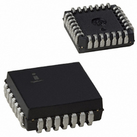
CS82C5296
Description
IC UART/BRG 5V 16MHZ 28-PLCC
Manufacturer
Intersil
Datasheet
1.IS82C52Z.pdf
(20 pages)
Specifications of CS82C5296
Features
Single Chip UART/BRG
Number Of Channels
1, UART
Protocol
RS232C
Voltage - Supply
4.5 V ~ 5.5 V
With Parallel Port
Yes
With False Start Bit Detection
Yes
With Modem Control
Yes
With Cmos
Yes
Mounting Type
Surface Mount
Package / Case
28-LCC (J-Lead)
Lead Free Status / RoHS Status
Contains lead / RoHS non-compliant
Fifo's
-
With Auto Flow Control
-
With Irda Encoder/decoder
-
Available stocks
Company
Part Number
Manufacturer
Quantity
Price


Reset
During and after power-up, the 82C52 Reset Input (RST)
must be held high for at least two IX clock cycles in order to
initialize and drive the 82C52 circuits to an idle mode until
proper programming can be done. A high on RST causes
the following events to occur
• Resets the internal Baud Rate Generator (BRG) circuit
• Clears the UART Status Register (USR) except for
Following removal of the reset condition (RST = low), the
82C52 remains in the idle mode until programmed to its
desired system configuration.
Programming The 82C52
The complete functional definition of the 82C52 is
programmed by the systems software. A set of control words
(UCR, BRSR and MCR) must be sent out by the CPU to
initialize the 82C52 to support the desired communication
format. These control words will program the character
length, number of stop bits, even/odd/no parity, baud rate,
etc. Once programmed, the 82C52 is ready to perform its
communication functions.
The control registers can be written to in any order. However,
the MCR should be written to last because it controls the
interrupt enables, modem control outputs and the receiver
enable bit. Once the 82C52 is programmed and operational,
these registers can be updated any time the 82C52 is not
immediately transmitting or receiving data.
Table 1. Shows the control signals required to access 82C52
internal registers.
UART Control Register (UCR)
The UCR is a write only register which configures the UART
transmitter and receiver circuits. Data bits D7 and D6 are not
used but should always be set to a logic zero (0) in order to
insure software compatibility with future product upgrades.
During the Echo Mode, the transmitter always repeats the
received word and parity, even when the UCR is
programmed with different or no parity. See Figure 1.
clock counters and bit counters. The Baud Rate Select
Register (BRSR) is not affected (except for bit 7 which is
reset to 0).
Transmission Complete (TC) and Transmit Buffer Register
Empty (TBRE) which are set. The Modem Control
Register (MCR) is also cleared. All of the discrete lines,
memory elements and miscellaneous logic associated
with these register bits are also cleared or turned off. Note
that the UART Control Register (UCR) is not affected.
5
82C52
82C52
Baud Rate Select Register (BRSR)
The 82C52 is designed to operate with a single crystal or
external clock driving the IX input pin. The Baud Rate Select
Register is used to select the divide ratio (one of 72) for the
internal Baud Rate Generator circuitry. The internal circuitry
is separated into two separate counters, a Prescaler and a
Divisor Select. The Prescaler can be set to any one of four
division rates, ÷1, ÷3, ÷4, or ÷5.
D7 D6 D5 D4 D3 D2 D1 D0
CS0
0
0
0
0
0
0
0
0
A1
0
0
0
0
1
1
1
1
A0
0
0
1
1
0
0
1
1
WR
0
1
0
1
0
1
0
1
FIGURE 1. UCR
TABLE 1.
RD
1
0
1
0
1
0
1
0
Data Bus → Transmitter Buffer
Register (TBR)
Receiver Buffer Register
(RBR) → Data Bus
Data Bus → UART Control
Register (UCR)
UART Status Register
(USR) → Data Bus
Data Bus → Modem Control
Register (MCR)
MCR → Data Bus
Data Bus → Bit Rate Select
Register (BRSR)
Modem Status Register
(MSR) → Data Bus
Stop Bit
Select
Parity
Control
Word
Length
Select
Reserved Set to 00 for Future
OPERATION
0 = 1 Stop Bits
1 = 1.5 Stop Bits (Tx)
and 1 Stop Bit (Rx)
If 5 Data Bits Selected
1 = 2 Stop Bits for 6, 7
or 8 Data Bits Selected
000 = Tx and Rx Even
001 = Tx and Rx Odd
010 = Tx Even, Rx
Odd
011 = Tx Odd, Rx
Even
100 = Tx Even, Rx
Check Disabled
101 = Tx Odd, Rx
Check Disabled
11X = Generation and
Check Disabled
00 = 5 Bits
01 = 6 Bits
10 = 7 Bits
11 = 8 Bits
Product Upgrade
Compatibility
April 26, 2006
FN2950.3
Related parts for CS82C5296
Image
Part Number
Description
Manufacturer
Datasheet
Request
R

Part Number:
Description:
Intersil Corporation [CMOS Serial Controller Interface]
Manufacturer:
Intersil Corporation
Datasheet:
Part Number:
Description:
Manufacturer:
Intersil Corporation
Datasheet:
Part Number:
Description:
357-036-542-201 CARDEDGE 36POS DL .156 BLK LOPRO
Manufacturer:
Intersil Corporation
Datasheet:
Part Number:
Description:
1024-Word x 4-Bit LSI Static RAM
Manufacturer:
Intersil Corporation
Datasheet:
Part Number:
Description:
General Purpose NPN Transistor Arrays FN341.4
Manufacturer:
Intersil Corporation
Datasheet:
Part Number:
Description:
CMOS 16-Bit Microprocessor
Manufacturer:
Intersil Corporation
Datasheet:
Part Number:
Description:
Manufacturer:
Intersil Corporation
Datasheet:
Part Number:
Description:
Manufacturer:
Intersil Corporation
Datasheet:
Part Number:
Description:
Manufacturer:
Intersil Corporation
Datasheet:
Part Number:
Description:
Manufacturer:
Intersil Corporation
Datasheet:
Part Number:
Description:
CMOS 6-Bit Latch and Decoder Memory Interfaces
Manufacturer:
Intersil Corporation
Datasheet:
Part Number:
Description:
CA3046General Purpose NPN Transistor Arrays
Manufacturer:
Intersil Corporation
Datasheet:
Part Number:
Description:
Manufacturer:
Intersil Corporation
Datasheet:
Part Number:
Description:
TR909 DLC/FLC SLIC with Low Power Standby
Manufacturer:
Intersil Corporation
Datasheet:
Part Number:
Description:
Manufacturer:
Intersil Corporation
Datasheet: