HDL36100 SQUARE D, HDL36100 Datasheet - Page 46
HDL36100
Manufacturer Part Number
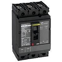
HDL36100
Description
CIRCUIT BREAKER, THERMAL MAG, 3P, 100A
Manufacturer
SQUARE D
Series
PowerPactr
Type
Standardr
Specifications of HDL36100
Actuator Style
Toggle
No. Of Poles
3
Current Rating
100A
Voltage Rating Vdc
250V
Voltage Rating Vac
600V
Mounting Type
DIN Rail
Terminals
Lug
Actuator Type
Handle
Brand/series
HD Series
Characteristic
Adjustable Trip
Dimensions
6.40 (H) × 4.12 (W) × 4.36 (D) in.
Frame Type
H
Number Of Poles
3
Terminal Type
Line: Lug - Load: Lug
Voltage Rating
600/250 VAC/DC
Weight
5.00 lbs.
Wire Size
#14-3/0 AWG (Al/Cu)
Ampere Interrupting Ratings
25 k @ 240 VAC, 18k @ 480 VAC
Standards
UL489, CSA, NOM, IEC 60947, CE
Lead Free Status / RoHS Status
Lead free / RoHS Compliant


46
PowerPact
Section 4—Wiring Diagrams
Figure 14:
11 grey
12 yellow
14 violet
C1 white
OR / O / OU
D1 white
Color wiring legend
BPO
(open)
AC Input Common, DC Negative (-)
OF1 / AX
AC Input Common, DC Positive (+)
06/2010
A4
Motor Mechanism Module
A1
MN / UVR
MX / SHT
BPF
(close)
Standard Motor Operator Control Wiring
91 black
92 green
94 red
C2 orange
D4 blue
®
A2
SD / AL
H- and J-Frame Circuit Breakers
SDE
OAL
B2
Standard Motor Operator Wiring (Factory Wiring Configuration)
A circuit breaker may be configured for remote operations. Remotely operated circuit breakers are
factory wired for the power supply to the motor being switched by the overcurrent trip switch. This
prevents the circuit breaker from being remotely reset after an overload fault as a precaution against
closing on a fault.
Remote Reset Wiring Without Overcurrent Trip Switch Protection
To configure circuit breaker for remote operation without overcurrent switch protection, follow the
wiring diagram below.
Figure 15:
BPO
(open)
AC Input Voltage, DC Positive (+)
AC Input Common, DC Negative (-)
L1
A4
Motor Mechanism Module
82
A1
BPF
(close)
H2
Motor Operator Without Overcurrent Switch Protection
A2
B4
81
84
H1
B2
Connector
L1
Indicator
B4
B2
B4 blue
A4
A2
B4
A1
L1
84
H1
H2
H1
Description
Electrical opening (positive DC)
Electrical closing (positive DC)
Power supply connection (positive DC)
Power supply connection (negative DC)
Automatic position indicator
Overcurrent trip indicator
Lamp signal indicating MCH in automatic position
Lamp signal indicating overcurrent trip condition
A2
84 red
A4 orange
SDE / OAL
white
21 grey
22 yellow
24 violet
L1 green
A1 black
OF2 / AX
© 2004–2010 Schneider Electric
All Rights Reserved
Related parts for HDL36100
Image
Part Number
Description
Manufacturer
Datasheet
Request
R


Part Number:
Description:
Pushbutton, Non-Illum'd Red "STOP", Momentary, 1NO-1NC, Square 30mm, 10A, 600V
Manufacturer:
SQUARE D
Datasheet:

Part Number:
Description:
KITS,TWIDO? PROGRAMMABLE CONTROLLERS,KITS,TWIDOPACK STARTER KIT - ADVANCED LEVEL,PROGRAMMABLE CONTROLLERS,TWIDO? PROGRAMMABLE CONTROLLERS ,SQUARE D
Manufacturer:
SQUARE D

Part Number:
Description:
LAMPS,INDICATOR,STACKABLE,LAMPS, STACKABLE INDICATOR,VISUAL INDICATING SIGNALS,XVB SERIES INDICATING BANKS ,SQUARE D
Manufacturer:
SQUARE D
Part Number:
Description:
LAMPS,INDICATOR,STACKABLE,LAMPS, STACKABLE INDICATOR,VISUAL INDICATING SIGNALS,XVB SERIES INDICATING BANKS ,SQUARE D
Manufacturer:
SQUARE D
Datasheet:
Part Number:
Description:
I/O EXTENDER MODULE 4 D IN & 2 D OUTPUT
Manufacturer:
SQUARE D
Datasheet:
Part Number:
Description:
CB ACCESSORY, UNDERVOLTAGE TRIP 48V DC
Manufacturer:
SQUARE D
Datasheet: