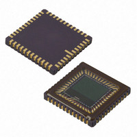
MT9T031C12STC Aptina LLC, MT9T031C12STC Datasheet - Page 26

MT9T031C12STC
Manufacturer Part Number
MT9T031C12STC
Description
IC SENSOR IMAGE COLOR 48CLCC
Manufacturer
Aptina LLC
Series
Micron®DigitalClarity®r
Type
CMOS Imagingr
Datasheets
1.MT9T031C12STCH_ES.pdf
(12 pages)
2.MT9T031C12STCH_ES.pdf
(2 pages)
3.MT9T031C12STC.pdf
(2 pages)
4.MT9T031C12STC.pdf
(46 pages)
Specifications of MT9T031C12STC
Pixel Size
3.2µm x 3.2µm
Active Pixel Array
2048H x 1536V
Frames Per Second
12 ~ 93
Voltage - Supply
3 V ~ 3.6 V
Package / Case
48-CLCC
Brief Features
Superior Low Light Performance, Programmable Controls, Low Dark Current, High Frame Rate
Supply Voltage Range
3V To 3.6V
Operating Temperature Range
0°C To +60°C
Ic Function
Digital Image Sensor
Lead Free Status / RoHS Status
Lead free / RoHS Compliant
For Use With
557-1450 - KIT HEAD BOARD FOR MT9T031557-1451 - KIT DEV FOR MT9T031
Lead Free Status / Rohs Status
Compliant
Other names
557-1452
Available stocks
Company
Part Number
Manufacturer
Quantity
Price
Part Number:
MT9T031C12STC
Manufacturer:
APTINA
Quantity:
20 000
Pixel Integration Time Control
Snapshot Mode and Flash Control
Setting up for Snapshot Mode
Triggering A Snapshot
PDF: 3682685119/Source: 9830567334
MT9T031_DS - Rev.E 5/11 EN
1. External TRIGGER Pulse
2. TRIGGER from Register Setting
R0x09 and R0x0C
The integration time of the pixel is the amount of time the pixels are set to collect charge
generated from light. The user can change the integration time of the sensor by
programming R0x09. The value of R0x09 sets the number of row time for integration.
The sensor also supports sub-row integration time for fine control of pixel integration
time.
The formula for calculating the pixel integration time is (reference Table 4 on page 12 for
P1 description):
t
Typically, the value of R0x09 is limited to the number of rows per frame (which includes
vertical blanking rows), such that the frame rate is not affected by the integration time.
However, if R0x09 is increased beyond the total number of rows per frame, then addi-
tional blanking rows are added as needed.
While the user can adjust the integration time to the desired value according to the
aforementioned formula, not all integration times may be desired under certain lighting
conditions. If the light source has a flicker component, then the integration time needs
to be set properly to avoid banding in the image.
Under 60Hz flicker, the integration time must be a multiple of 1/120 of a second to avoid
flicker. Under 50Hz flicker, the integration time must be a multiple of 1/100 of a second
to avoid flicker.
R0x1E, STROBE pin and TRIGGER pin
Snapshot mode must be enabled before use by setting bit 8 = “1” of R0x1E. There are two
important signals used for snapshot mode: TRIGGER and STROBE. The TRIGGER signal
initiates the start of a single frame capture and STROBE is an output pulse that may be
used to turn on a flash and/or activate a mechanical shutter.
The TRIGGER signal required for starting a frame capture may be generated in the
following two ways:
INT
Pin 8 is a digital input that may be used to supply an external trigger signal input. The
snapshot operation begins after the TRIGGER pulse transitions from a HIGH to LOW
state.
A second method for triggering a snapshot is by setting bit 0 = 1 of R0x0B (Restart).
This register automatically returns bit 0 to “0” after the TRIGGER is initiated. This bit
does not need to be reset by the user after use.
= (65536 x R0x08 + R0x09) x
26
t ROW
-R0x0C-P1+132
MT9T031: 1/2-Inch 3-Mp Digital Image Sensor
©2006 Aptina Imaging Corporation. All rights reserved.
Feature Description


