MT9T031C12STC Aptina LLC, MT9T031C12STC Datasheet - Page 35
MT9T031C12STC
Manufacturer Part Number
MT9T031C12STC
Description
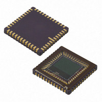
IC SENSOR IMAGE COLOR 48CLCC
Manufacturer
Aptina LLC
Series
Micron®DigitalClarity®r
Type
CMOS Imagingr
Datasheets
1.MT9T031C12STCH_ES.pdf
(12 pages)
2.MT9T031C12STCH_ES.pdf
(2 pages)
3.MT9T031C12STC.pdf
(2 pages)
4.MT9T031C12STC.pdf
(46 pages)
Specifications of MT9T031C12STC
Pixel Size
3.2µm x 3.2µm
Active Pixel Array
2048H x 1536V
Frames Per Second
12 ~ 93
Voltage - Supply
3 V ~ 3.6 V
Package / Case
48-CLCC
Brief Features
Superior Low Light Performance, Programmable Controls, Low Dark Current, High Frame Rate
Supply Voltage Range
3V To 3.6V
Operating Temperature Range
0°C To +60°C
Ic Function
Digital Image Sensor
Lead Free Status / RoHS Status
Lead free / RoHS Compliant
For Use With
557-1450 - KIT HEAD BOARD FOR MT9T031557-1451 - KIT DEV FOR MT9T031
Lead Free Status / Rohs Status
Compliant
Other names
557-1452
Available stocks
Company
Part Number
Manufacturer
Quantity
Price

Part Number:
MT9T031C12STC
Manufacturer:
APTINA
Quantity:
20 000


Gain Settings
Table 13:
Black Level Calibration
Manual Black Level Calibration
PDF: 3682685119/Source: 9830567334
MT9T031_DS - Rev.E 5/11 EN
Gain Increment Settings
R0x2B, R0x2C, R0x2D, R0x2E, and R0x35
The analog programmable gain stage consists of two stages of gain circuitry that operate
in a pipelined manner. The first stage of gain has programmable gain of 1 or 2 while the
second stage of gain has programmable gain of 1 to 4 with steps of 0.125 for a maximum
analog gain of 8. The gain settings can be independently adjusted for the colors of
Green1, Blue, Red, and Green2 and are programmed through R0x2B, R0x2C, R0x2D, and
R0x2E, respectively. The gain may also be adjusted globally through R0x35. The first
stage of gain is set by Bit(6), while the second stage gain is set by Bit(5
individually controllable for each color in the Bayer pattern as follows:
Analog Gain < = 8:
Gain = (Bit[6] + 1) x (Bit[5:0] x 0.125)
Digital Gain = 1 + Bit[14:8]/8
Total Gain = Analog Gain x Digital Gain
Since Bit[6] of the gain registers are multiplicative factors for the gain settings, there are
alternative ways of achieving certain gains. Some settings offer superior noise perfor-
mance to others, despite the same overall gain, as shown in Table 13.
R0x5D, and R0x5F
The digitized black level of the MT9T031 sensor potentially varies with temperature or
gain setting changes. The MT9T031 sensor allows the user the flexibility of automatic
black level calibration or manual black level control.
R0x60, R0x61, R0x62, R0x63, and R0x64
The programmable analog offset stage corrects for analog offset that might be present in
the analog signal. The user would need to program R0x62 appropriately to enable the
analog offset correction. The analog offset settings can be independently adjusted for
the colors of Green1, Green2, Red and Blue and are programmed through R0x60, R0x61,
R0x63 and R0x64 respectively. Bit[8] of R0x60, R0x61, R0x63 and R0x64 (these registers
have two’s complement representation) determines the sign of the analog offset. Bit[8] =
1 makes the analog correction negative instead of positive.
The lower 8 bits (Bit[7:0]) determine the absolute value of the analog offset to be
corrected and Bit[8] determines the sign of the correction. When Bit[8] is “1”, the sign of
the correction is negative and vice versa. The analog value of the correction relative to
the analog gain stage can be determined from the following formula:
Nominal Gain
4.25 to 8.00
9.0 to 128.0
1 to 4.000
35
MT9T031: 1/2-Inch 3-Mp Digital Image Sensor
Increments
0.125
0.25
1.0
©2006 Aptina Imaging Corporation. All rights reserved.
Recommended Settings
0x0008 to 0x0020
0x0051 to 0x0060
0x0160 to 0x7860
Feature Description
–
0). The gain is
Related parts for MT9T031C12STC
Image
Part Number
Description
Manufacturer
Datasheet
Request
R

Part Number:
Description:
SENSOR IMAGE VGA COLOR CMOS PLCC
Manufacturer:
Aptina LLC
Datasheet:

Part Number:
Description:
SENSOR IMAGE 1.3MP CMOS 48-CLCC
Manufacturer:
Aptina LLC
Datasheet:

Part Number:
Description:
SENSOR IMAGE 2MP CMOS 48-CLCC
Manufacturer:
Aptina LLC
Datasheet:

Part Number:
Description:
SENSOR IMAGE VGA MONO 52IBGA
Manufacturer:
Aptina LLC
Datasheet:

Part Number:
Description:
SENSOR IMAGE VGA COLOR 48CLCC
Manufacturer:
Aptina LLC
Datasheet:

Part Number:
Description:
SENSOR IMAGE COLOR CMOS 48-PLCC
Manufacturer:
Aptina LLC
Datasheet:

Part Number:
Description:
KIT HEAD BOARD FOR MT9P031
Manufacturer:
Aptina LLC
Datasheet:

Part Number:
Description:
KIT HEAD BOARD FOR MT9D131
Manufacturer:
Aptina LLC
Datasheet:

Part Number:
Description:
KIT HEAD BOARD FOR MT9P031
Manufacturer:
Aptina LLC
Datasheet:

Part Number:
Description:
KIT HEAD BOARD FOR MT9M032
Manufacturer:
Aptina LLC
Datasheet:

Part Number:
Description:
PARALLEL HEADBOARD FOR MT9M032
Manufacturer:
Aptina LLC
Datasheet:
Part Number:
Description:
SENSOR IMAGE VGA COLOR CMOS PLCC
Manufacturer:
Aptina LLC
Datasheet:
Part Number:
Description:
SENSOR IMAGE 2MP CMOS 48-CLCC
Manufacturer:
Aptina LLC
Datasheet:
