MT9T031C12STC Aptina LLC, MT9T031C12STC Datasheet - Page 28
MT9T031C12STC
Manufacturer Part Number
MT9T031C12STC
Description
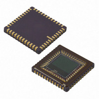
IC SENSOR IMAGE COLOR 48CLCC
Manufacturer
Aptina LLC
Series
Micron®DigitalClarity®r
Type
CMOS Imagingr
Datasheets
1.MT9T031C12STCH_ES.pdf
(12 pages)
2.MT9T031C12STCH_ES.pdf
(2 pages)
3.MT9T031C12STC.pdf
(2 pages)
4.MT9T031C12STC.pdf
(46 pages)
Specifications of MT9T031C12STC
Pixel Size
3.2µm x 3.2µm
Active Pixel Array
2048H x 1536V
Frames Per Second
12 ~ 93
Voltage - Supply
3 V ~ 3.6 V
Package / Case
48-CLCC
Brief Features
Superior Low Light Performance, Programmable Controls, Low Dark Current, High Frame Rate
Supply Voltage Range
3V To 3.6V
Operating Temperature Range
0°C To +60°C
Ic Function
Digital Image Sensor
Lead Free Status / RoHS Status
Lead free / RoHS Compliant
For Use With
557-1450 - KIT HEAD BOARD FOR MT9T031557-1451 - KIT DEV FOR MT9T031
Lead Free Status / Rohs Status
Compliant
Other names
557-1452
Available stocks
Company
Part Number
Manufacturer
Quantity
Price

Part Number:
MT9T031C12STC
Manufacturer:
APTINA
Quantity:
20 000


Bulb Mode
Skip and Bin Modes
Table 11:
PDF: 3682685119/Source: 9830567334
MT9T031_DS - Rev.E 5/11 EN
1,024 x 768
XGA
800 x 600
SVGA
640 x 480
VGA
Resolu-
tion
Bin and Skip Mode Resolution
Frame
34 fps
50 fps
48 fps
Rate
Note:
Note:
Column_
(R0
2,047
1,599
1,919
Size
1. Set up snapshot mode as normal (including any STROBE preferences).
2. Set R0x21 (Read Mode 3) to 0x0001.
3. Assert (transition LOW to HIGH) the GSHT_CTL pin.
4. Assert (transition LOW to HIGH) the TRIGGER pin to reset the array. This pin must
5. Negate (transition HIGH to LOW) the GSHT_CTL pin to begin the exposure. The
6. Negate (transition HIGH to LOW) the TRIGGER pin to begin row read out. The
To use bulb mode:
Row and column skip modes use subsampling to reduce the output resolution without
reducing field-of-view. The MT9T031 also has row and column binning modes, which
can reduce the impact of aliasing introduced by the use of skip modes. This is achieved
by the averaging of two or three adjacent rows and columns (adjacent same-color
pixels). Both 2X and 3X binning modes are supported. Rows and columns can be binned
independently.
To use binning mode, set R0x22[5–4] (row bin) or R0x23[5–4] (column bin) to the desired
reduction minus 1, as would be done for skip mode. Additionally, R0x22[2–0] (column
skip) must be set no less than R0x22[5–4], and R0x23[2–0] (row skip) must be set no less
than R0x23[5–4]. Row and column skip modes may be set higher than the corresponding
binning modes to achieve greater reductions, but binning must be done. The different
skip modes supported are between 2X and 8X in both column and row directions. The
different binning modes supported are 2X and 3X. See Table 12 for register bits control-
ling the different bin and skip modes.
x
04)
remain HIGH for at least 18,820 PIXCLKs.
exposure starts 1,000 PIXCLKs after the falling edge of GSHT_CTL.
Unlike normal snapshot mode, R0x0B (Restart) may not be used to initiate the expo-
sure in global shutter modes.
mechanical shutter should be closed before row read out begins. The trailing edge of
STROBE (if enabled) occurs ((65536 x R0x08 + R0x09) x
edge of TRIGGER. Read out of the active window starts the lesser of 16 x
(R0x06 + 1) x
mally be set to a low number, allowing row readout to start immediately after the trail-
ing edge of TRIGGER.
Column start address value must be a multiple of R0x23 [5–4] + 1.
(R0
Row_
1,535
1,199
1,439
Size
x
03)
t
ROW
Horizontal_
(R0
later. In this mode, the shutter width (R0x08, R0x09) would nor-
Blank
22
22
21
x
05)
28
Vertical_
(R0
Blank
40
30
31
x
06)
MT9T031: 1/2-Inch 3-Mp Digital Image Sensor
(R0
Row_
Bin
1
1
2
x
22)
(R0
Row_
Skip
t
1
1
2
x
ROW
22)
) PIXCLKs after the falling
©2006 Aptina Imaging Corporation. All rights reserved.
Column_
(R0
Bin
Feature Description
1
1
2
x
23)
t
ROW
Column_
(R0
Skip
1
1
2
x
or
23)
Related parts for MT9T031C12STC
Image
Part Number
Description
Manufacturer
Datasheet
Request
R

Part Number:
Description:
SENSOR IMAGE VGA COLOR CMOS PLCC
Manufacturer:
Aptina LLC
Datasheet:

Part Number:
Description:
SENSOR IMAGE 1.3MP CMOS 48-CLCC
Manufacturer:
Aptina LLC
Datasheet:

Part Number:
Description:
SENSOR IMAGE 2MP CMOS 48-CLCC
Manufacturer:
Aptina LLC
Datasheet:

Part Number:
Description:
SENSOR IMAGE VGA MONO 52IBGA
Manufacturer:
Aptina LLC
Datasheet:

Part Number:
Description:
SENSOR IMAGE VGA COLOR 48CLCC
Manufacturer:
Aptina LLC
Datasheet:

Part Number:
Description:
SENSOR IMAGE COLOR CMOS 48-PLCC
Manufacturer:
Aptina LLC
Datasheet:

Part Number:
Description:
KIT HEAD BOARD FOR MT9P031
Manufacturer:
Aptina LLC
Datasheet:

Part Number:
Description:
KIT HEAD BOARD FOR MT9D131
Manufacturer:
Aptina LLC
Datasheet:

Part Number:
Description:
KIT HEAD BOARD FOR MT9P031
Manufacturer:
Aptina LLC
Datasheet:

Part Number:
Description:
KIT HEAD BOARD FOR MT9M032
Manufacturer:
Aptina LLC
Datasheet:

Part Number:
Description:
PARALLEL HEADBOARD FOR MT9M032
Manufacturer:
Aptina LLC
Datasheet:
Part Number:
Description:
SENSOR IMAGE VGA COLOR CMOS PLCC
Manufacturer:
Aptina LLC
Datasheet:
Part Number:
Description:
SENSOR IMAGE 2MP CMOS 48-CLCC
Manufacturer:
Aptina LLC
Datasheet:
