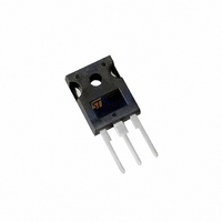
STPS40H100CW STMicroelectronics, STPS40H100CW Datasheet - Page 3

STPS40H100CW
Manufacturer Part Number
STPS40H100CW
Description
DIODE SCHOTTKY 100V 20A TO-247
Manufacturer
STMicroelectronics
Specifications of STPS40H100CW
Voltage - Forward (vf) (max) @ If
730mV @ 20A
Current - Reverse Leakage @ Vr
10µA @ 100V
Current - Average Rectified (io) (per Diode)
20A
Voltage - Dc Reverse (vr) (max)
100V
Diode Type
Schottky
Speed
Fast Recovery =< 500ns, > 200mA (Io)
Diode Configuration
1 Pair Common Cathode
Mounting Type
Through Hole, Radial
Package / Case
TO-247-3
Configuration
Common Cathode
Current, Forward
40 A
Current, Reverse
1 A
Current, Surge
300 A
Package Type
TO-247
Primary Type
Rectifier
Resistance, Thermal, Junction To Case
0.55 °C/W
Speed, Switching
Switching
Temperature, Junction, Maximum
+175 °C
Voltage, Forward
0.85 V
Voltage, Reverse
100 V
Lead Free Status / RoHS Status
Lead free / RoHS Compliant
Reverse Recovery Time (trr)
-
Lead Free Status / Rohs Status
RoHS Compliant part
Electrostatic Device
Other names
497-2725-5
Available stocks
Company
Part Number
Manufacturer
Quantity
Price
Company:
Part Number:
STPS40H100CW
Manufacturer:
ST
Quantity:
1 250
Part Number:
STPS40H100CW
Manufacturer:
ST
Quantity:
20 000
Fig. 5: Non repetitive surge peak forward current ver-
sus overload duration (maximum values, per diode).
Fig. 7: Reverse leakage current versus reverse
voltage applied (maximum values, per diode).
400
350
300
250
200
150
100
1E+1
1E+0
Fig. 9:
current (per diode).
200
100
1E-1
1E-2
1E-3
1E-4
50
10
1E-3
0
1
0.0
IM(A)
IFM(A)
0
IR(mA)
I
M
0.2
10
Maximum values
Forward voltage drop versus forward
=0.5
t
Tj=125°C
0.4
20
Typical values
Tj=125°C
1E-2
30
0.6
40
0.8
VFM(V)
Tj=125°C
Tj=100°C
Tj=75°C
VR(V)
Tj=25°C
t(s)
50
Maximum values
1.0
Tj=25°C
60
1E-1
1.2
70
1.4
80
1.6
Tc=50°C
Tc=100°C
Tc=150°C
90 100
1E+0
1.8
Fig. 6: Relative variation of thermal impedance
junction to case versus pulse duration.
Fig. 8: Junction capacitance versus reverse
voltage applied (typical values, per diode).
1.0
0.8
0.6
0.4
0.2
0.0
3.0
1.0
0.1
1E-3
1
C(nF)
Zth(j-c)/Rth(j-c)
= 0.2
= 0.5
= 0.1
Single pulse
2
1E-2
5
VR(V)
tp(s)
10
STPS40H100CW
1E-1
20
=tp/T
50
F=1MHz
Tj=25°C
T
tp
1E+0
100
3/4


