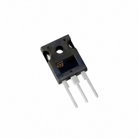
STGW19NC60WD STMicroelectronics, STGW19NC60WD Datasheet - Page 5

STGW19NC60WD
Manufacturer Part Number
STGW19NC60WD
Description
IGBT N-CH 23A 600V TO-247
Manufacturer
STMicroelectronics
Series
PowerMESH™r
Datasheet
1.STGP19NC60WD.pdf
(15 pages)
Specifications of STGW19NC60WD
Voltage - Collector Emitter Breakdown (max)
600V
Vce(on) (max) @ Vge, Ic
2.5V @ 15V, 12A
Current - Collector (ic) (max)
42A
Power - Max
125W
Input Type
Standard
Mounting Type
Through Hole
Package / Case
TO-247-3
Configuration
Single
Collector- Emitter Voltage Vceo Max
600 V
Maximum Gate Emitter Voltage
+/- 20 V
Maximum Operating Temperature
+ 150 C
Continuous Collector Current Ic Max
42 A
Minimum Operating Temperature
- 55 C
Mounting Style
Through Hole
Transistor Type
IGBT
Dc Collector Current
42A
Collector Emitter Voltage Vces
2.5V
Power Dissipation Pd
125W
Collector Emitter Voltage V(br)ceo
600V
Operating Temperature Range
-55°C To +150°C
Rohs Compliant
Yes
Channel Type
N
Collector-emitter Voltage
600V
Collector Current (dc) (max)
42A
Gate To Emitter Voltage (max)
±20V
Package Type
TO-247
Pin Count
3 +Tab
Mounting
Through Hole
Operating Temperature (min)
-55C
Operating Temperature (max)
150C
Operating Temperature Classification
Military
Lead Free Status / RoHS Status
Lead free / RoHS Compliant
Igbt Type
-
Lead Free Status / Rohs Status
Lead free / RoHS Compliant
Other names
497-7483-5
STGW19NC60WD
STGW19NC60WD
STGP19NC60WD - STGW19NC60WD
Table 5.
Table 6.
1. Eon is the turn-on losses when a typical diode is used in the test circuit in
2. Turn-off losses include also the tail of the collector current
Symbol
(di/dt)
(di/dt)
Symbol
t
t
E
E
E
E
t
t
t
t
r
r
in a package with a co-pak diode, the co-pack diode is used as external diode. IGBTs & Diode are at the
same temperature (25°C and 125°C)
d
d
d(on)
d(on)
(V
(V
E
E
on
off
on
off
(
(
t
t
t
t
off
off
r
r
f
f
ts
ts
off
off
(1)
(2)
(1)
(2)
on
on
)
)
)
)
Turn-on delay time
Current rise time
Turn-on current slope
Turn-on delay time
Current rise time
Turn-on current slope
Off voltage rise time
Turn-off delay time
Current fall time
Off voltage rise time
Turn-off delay time
Current fall time
Turn-on switching losses
Turn-off switching losses
Total switching losses
Turn-on switching losses
Turn-off switching losses
Total switching losses
Switching on/off (inductive load)
Switching energy (inductive load)
Parameter
Parameter
V
R
Figure 17
V
R
Tj = 125°C
Figure 17
V
R
Figure 17
V
R
Tj = 125°C
Figure 17
V
R
Figure 17
V
R
Tj = 125°C
Figure 17
CC
CC
G
G
CC
CC
CC
CC
G
G
G
G
= 10Ω , V
= 10Ω , V
= 10Ω , V
= 10Ω , V
= 10Ω , V
= 10Ω , V
= 390V, I
= 390V, I
= 390V, I
= 390V, I
= 390V, I
= 390V, I
Test conditions
Test conditions
GE
GE
GE
GE
GE
GE
C
C
C
C
C
C
= 15V,
= 15V,
= 15V,
= 15V,
= 15V,
= 15V,
= 12A
= 12A
= 12A
= 12A
= 12A
= 12A
Figure 15
Electrical characteristics
Min.
Min.
If the IGBT is offered
1600
1400
Typ.
Typ.
127
125
206
161
255
416
25
25
22
90
43
47
77
81
7
8
Max.
Max.
A/µs
A/µs
Unit
Unit
ns
ns
ns
ns
ns
ns
ns
ns
ns
ns
µJ
µJ
µJ
µJ
µJ
µJ
5/15


