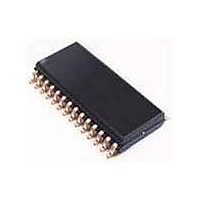
PCK2002MPW-T NXP Semiconductors, PCK2002MPW-T Datasheet - Page 5

PCK2002MPW-T
Manufacturer Part Number
PCK2002MPW-T
Description
Clock Buffer 14.318-167MHZ I2C 1:10CLK BUFR
Manufacturer
NXP Semiconductors
Datasheet
1.PCK2002MPW-T.pdf
(12 pages)
Specifications of PCK2002MPW-T
Number Of Outputs
10
Operating Supply Voltage (max)
3.465V
Operating Temp Range
0C to 70C
Propagation Delay Time
5ns
Operating Supply Voltage (min)
3.135V
Mounting
Surface Mount
Pin Count
28
Operating Supply Voltage (typ)
3.3V
Package Type
TSSOP
Quiescent Current
100uA
Input Frequency
133MHz
Duty Cycle
55%
Operating Temperature Classification
Commercial
Max Input Freq
133 MHz
Propagation Delay (max)
2.7 ns
Supply Voltage (max)
3.465 V
Supply Voltage (min)
3.135 V
Maximum Operating Temperature
+ 70 C
Minimum Operating Temperature
0 C
Mounting Style
SMD/SMT
Package / Case
TSSOP-28
Lead Free Status / RoHS Status
Compliant
Other names
PCK2002MPW,118
1. Skew is measured on the rising edge at 1.5 V.
2. T
3. Duty cycle should be tested with a 50/50% input.
4. Over MIN (20 pF) to MAX (30 pF) discrete load, process, voltage, and temperature.
5. Input edge rate for these tests must be faster than 1 V/ns.
6. Calculated at minimum edge rate (1.5 ns) to guarantee 45/55% duty cycle at 1.5 V. Pulsewidth is required to be wider at the faster edge to
7. All typical values are at V
8. Typical is measured with MAX (30 pF) discrete load.
9. Typical is measured with MIN (20 pF) discrete load.
Philips Semiconductors
AC CHARACTERISTICS
NOTES:
2001 Jul 19
DUTY CYCLE
0–300 MHz I
T
T
ensure duty cycle specification is met.
SYMBOL
T
T
PZL
PLZ
T
T
SDRISE
SDRISE
SDFALL
SDSKW
DDSKW
T
T
PLH
PHL
, T
, T
PZH
PHZ
and T
SDFALL
SDRAM buffer LH propagation delay
SDRAM buffer HL propagation delay
SDRAM buffer disable time
SDRAM buffer enable time
2
are measured as a transition through the threshold region V
SDRAM Bus CLK skew
Device to device skew
C 1:10 clock buffer
CC
Output Duty Cycle
SDRAM rise time
SDRAM fall time
PARAMETER
= 3.3 V and T
amb
= 25 C.
Measured at 1.5 V
TEST CONDITIONS
5
NOTES
3, 4, 5
2, 4
2, 4
4, 5
4, 5
4, 5
4, 5
1, 4
OL
= 0.4 V and V
MIN
1.5
1.5
1.2
1.2
1.0
1.0
45
—
—
T
amb
OH
= 2.4 V (1 mA) JEDEC specification.
= 0 C to +70 C
LIMITS
TYP
150
2.0
2.9
2.7
2.7
2.6
2.7
52
—
7
PCK2002M
MAX
250
500
4.0
4.0
3.5
3.5
5.0
5.0
55
Product data
UNIT
V/ns
V/ns
ns
ns
ns
ns
ps
ps
%


